Smart Machine Smart Decision
SIM7600E_SIM7600E-H-PCIE_Hardware_Design_V1.00 32 2017-11-23
80
MODULE
79
GNSS_ANT
GND
78
GND
Matching circuit
GNSS ANT
L1
C1
56nH
33pF
10 ohm
33PF
100NF
PCIE
44
VDD_AUX
1.7V~3.05V
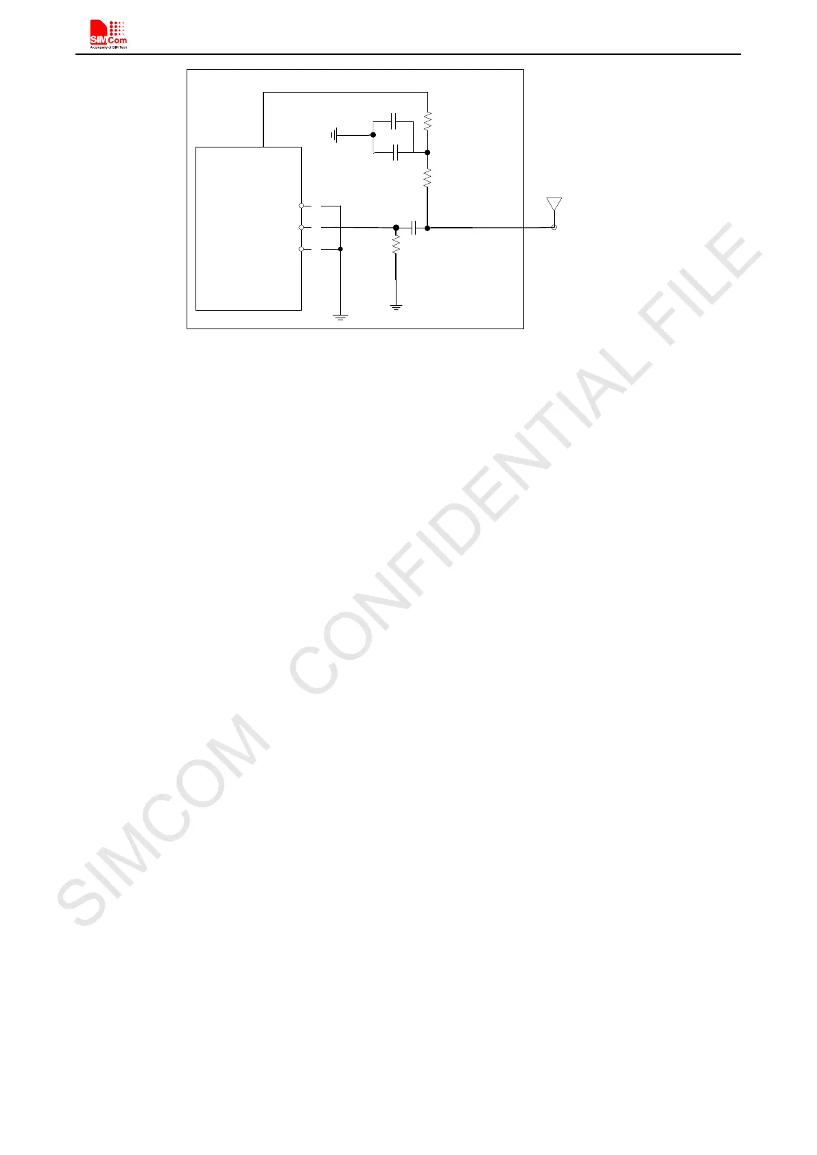
Figure 23: Active antenna circuit
In above Figure 23 the active antenna is used, If users want to change the voltage of VDD_AUX, use this AT
command; “AT+CVAUXV”. For example, if customer needs the output voltage value to be 1.8V, the AT
command should be “AT+CVAUXV=1800000”. The output voltage range of VDD_AUX is from 1.7V to
3.05V.
Note; For more details of AT commands about VDD_AUX, please refer to document [1].
Note: GNSS is closed by default, it could be started by AT+CGPS. The AT command has two parameters, the
first is on/off, and the second is GNSS mode. Default mode is standalone mode.
AGPS mode needs more support from the mobile telecommunication network. Please refer to document [22]
for more details.