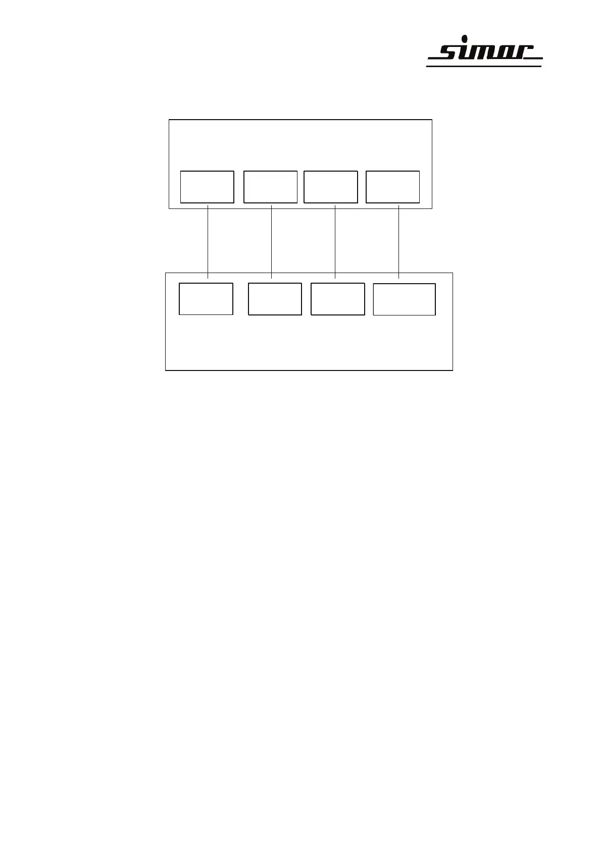
10 Terminal connection diagram for 3-phase motor
Attention: To prevent the risk of a short-circuit,
terminals L and N must not be interchanged !
11 Fuse
SI 1 and SI 2 6,3A respectively (slow-blowing) 1 spare is added part.
SI 3 1,0A (slow-blowing)
12 Technical data
Supply voltage: 230V AC / 50Hz
via a power supply cord with integral earthing-pin plug.
Motor connection: 230V AC / 4A
via motor connection cable with fitted socket connector.
Valve connection: 24 V DC / 0,5A
via valve cable with fitted solenoid valve connector (black)
Type of protection: IP54
Subject to change
Gebläsestarter
XS3
N
2
L1
3
L-Schalt
1PE
Relais-ON