9
Appliance package:
– combination boiler (assembled);
– installation and servicing instructions;
– users instructions;
– wall mounting templates (paper);
– wall mounting bracket;
– fixing screws with wall plugs;
– plastic bags containing:
– gas service cock;
– C.H. F/R isolation valves;
– D.H.W. isolation valve;
– D.H.W. elbow connection;
– associated fixing screws;
– associated gaskets;
– safety valve discharge pipe.
3.1 FIXING THE WALL MOUNTING BRACKET
Before installing the appliance ensure that the chosen loca-
tion is suitable (section 2.2) and that the requirements for
flue position, (section 2.3), and minimum clearances, (
Table 2
)
are satisfied. These minimum clearances are essential to pro-
vide access for servicing, and are included on the wall mount-
ing templates.
– Open the paper wall mounting templates. If a rear flue is
to be used, discard the side templates and secure the
rear template in the desired position. For a side flue appli-
cation, secure both the rear and appropriate side tem-
plate in position.
– Mark the position of the two wall mounting bracket fixing
holes and the flue/air duct hole on the appropriate wall(s).
– Remove the template(s) and drill the two fixing holes using
a 10 mm masonry drill. Fit the plastic plugs provided.
– Cut the hole in the wall for the flue/air duct. The diame-
ter should not be less than 100 mm (4 in) and must be
horizontal. Refer to fig. 12-14.
– Accurately measure the wall thickness, and note this
dimension for later use.
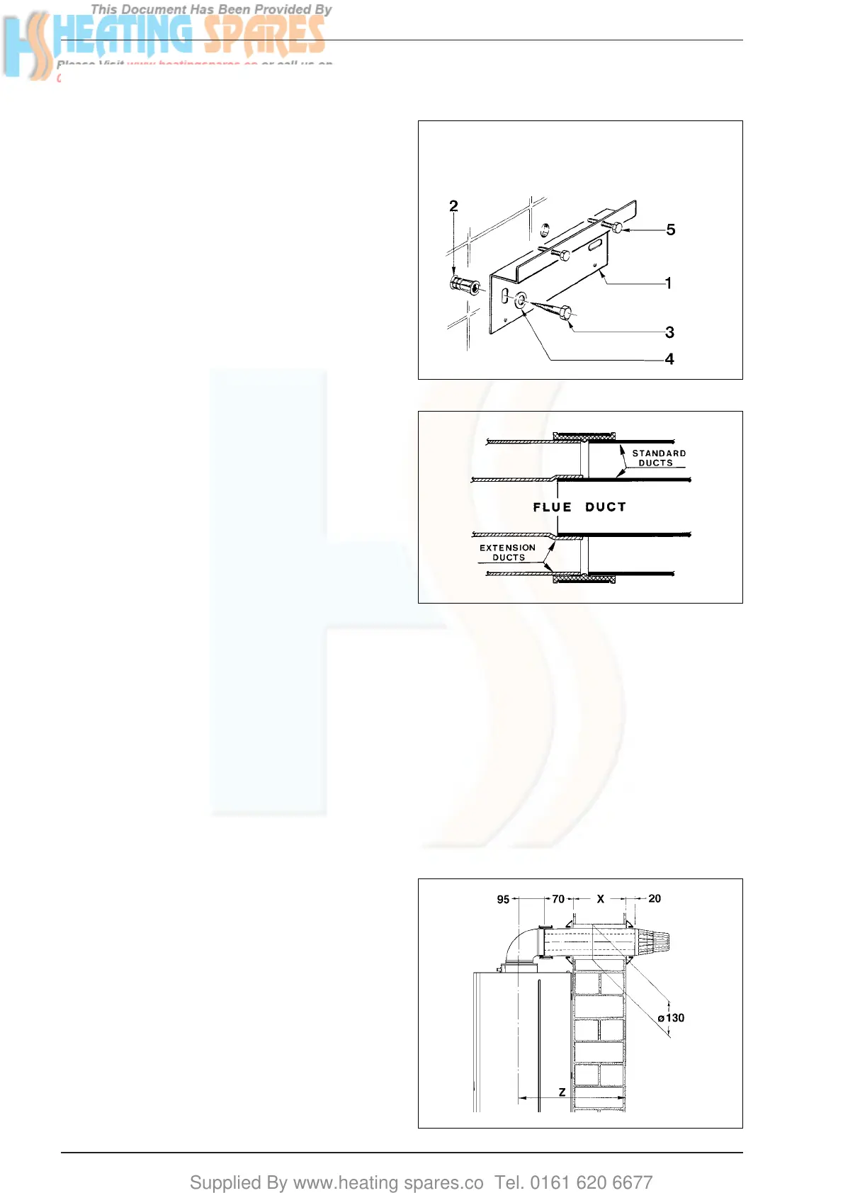
– Secure the wall mounting bracket in position using the
screws provided. Ensure that it is the correct way up, as
indicated in fig. 8.
3.2 HANGING THE BOILER
– Lift the appliance into position. The upper cross member
locates onto the wall mounting bracket.
– Screw in the wall mounting bracket adjusting screws until
the appliance is secure and vertical.
3.3 FLUE DUCTS PREPARATION
3.3.1 Flue/air duct lenghts
– Determine whether an extension duct is required with ref-
erence to the Z dimension shown in figs. 10-11.
– If no extension ducts are required, procede to 3.4.
–
If an extension duct or ducts is/are to be used, the flue and
air ducts should be joined before proceeding to the next sec-
tion. The extension ducts should be joined to each other and
to the standard ducts using the following procedure (fig. 9);
– For the flue ducts in turn, push the plain end of the stan-
dard and (if using two or three extensions) extension duct
into the swaged end of the extension duct(s).
– Push an air duct in to the clamp. Join the air ducts (larger
ducts) and tighten the screws an the clamp to connect them.
3.3.2 Cutting the flue/air duct extension
to the correct length
Rear flue outlet (Only - fig. 10)
– Select the air duct (larger duct) and starting at the formed
end, ‘mark off’ the length to be cut which is the wall thick-
ness X + 90 mm (3
1
/
2
in).
3 INSTALLING THE BOILER
Fig. 8
Fig. 9
Fig. 10
KEY
1 Wall mounting bracket
2 Plastic wall plug (2 Off)
3 Woodscrew (2 Off)
4 Washer (2 Off)
5 Adjustment screw (2 Off)