17
To ensure continued efficient operation of the appliance, it is
recommended that it is checked and serviced as necessary
at regular intervals. The frequency of servicing will depend
upon the particular installation conditions and usage but in
general once a year should be adequate.
It is the law that any service work must be carried out by reg-
istered personnel (C.O.R.G.I.). Before commencing any service
operation, ISOLATE the mains electrical supply, and TURN OFF
the gas supply at the main service cock. Service the appliance
by following the full procedure detailed below.
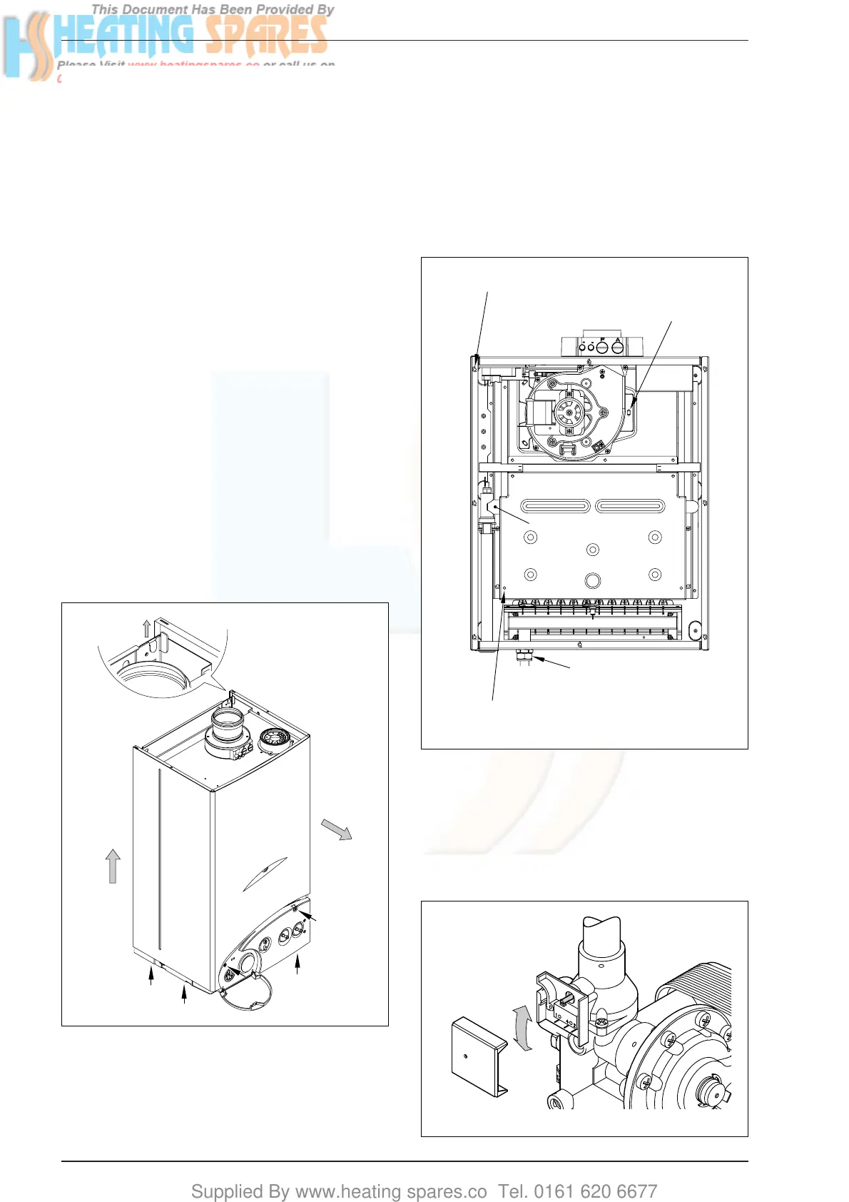
5.1 MAIN BURNER ASSEMBLY
– Remove the casing as showed in fig. 23.
– Remove the 8 fixing screws securing the sealed chamber
front panel then remove the panel.
– Unscrew the 7 screws securing the combustion chamber
front panel and remove the panel, taking care not to dam-
age the insulation.
– Remove the electrode by unscrewing it from the burner
manifold.
– Unscrew the burner manifold union and locking nut. Lift
the front of the burner to disengage manifold thread and
then lift the burner clear.
– Remove the burner manifold by disconnecting the four
screws.
– Inspect and if necessary, clean the injectors, electrodes,
and the main burner bars.
5.2 FAN ASSEMBLY
– Disconnect the electrical connections to the fan. Note the
position of the earth conductor.
– Remove the three screws securing the fan.
– Tilt the fan forwards and remove in a downwards direction.
– Inspect the fan assembly and clean if necessary.
5.3 HEAT EXCHANGER
– Inspect the heat exchanger, and clean if necessary.
5.4 WATER FLOW SWITCH
– Revome the cover from the micro assembly to gain
access to the flow switch spindle.
– Ensure the spindle is free to move (see fig. 25).
– Re-assemble the cover.
5 ROUTINE SERVICING INSTRUCTIONS