19
6.1 EARTH CONTINUITY CHECK
Appliances must be electrically disconnected, meter set on Ω
(ohm) x 1 scale and adjust zero if necessary. Tests leads from
any appliance earth point (e.g. inside control box) see wiring
diagrams (section 7) to earth pin on plug. Resistance should
be less than 1 Ω (ohm). If the resistance is greater than 1 Ω
(ohm) check all earth wires for continuity and all contacts are
clean and tight. If the resistance to earth is still greater than
1 Ω (ohm) then this should be investigated futher.
6.2 SHORT CIRCUIT CHECK
Switches turned FULL ON - meter set on Ω (ohms) x 1 scale.
Test leads from L to N on appliance terminal block, if meter
reads 0 then there is a short circuit.
Meter set on Ω (ohm) x 100 scale. Repeat it with leads from
L to E. If meter reads less than infinity (∞) there is a fault.
NOTE: Should it be found that the fuse has failed but no
fault is indicated, a detailed continuity check (i.e. by discon-
necting and checking each component) is required to trace
the faulty component.
It is possible that a fault could occur as a result of local
burning/arcing but no fault could be found under test.
However, a detailed visual inspection should reveal evi-
dence of burning around the fault.
6.3 POLARITY CHECK
Appliance reconnected to mains supply and meter set on
300 V ac scale. Test at appliance terminal block.
– Test leads from L to N meter reads approx.: 240 V ac.
– Test leads from L to E “ ” meter reads approx. 240 V ac.
–
Test leads from N to E “ ” meter reads from 0 to 15 V ac.
6.4 RESISTANCE TO EARTH CHECK
Appliance must be disconnected from main supply and meter
on Ω (ohm) x 100 scale.
All switches including thermostat on test leads from L to E - if
meter reads other than infinity (∞) there is a fault which
should be isolated. A detailed continuity check is required to
trace the faulty component.
IMPORTANT:
These series of checks are the first electrical checks to be
carried out during a fault finding procedure. On completion
of the service/fault finding task which has required the
breaking and remaking of electrical connections then the
checks 6.1 Earth continuity, 6.3 Polarity and 6.4
Resistance to earth must be repeated.
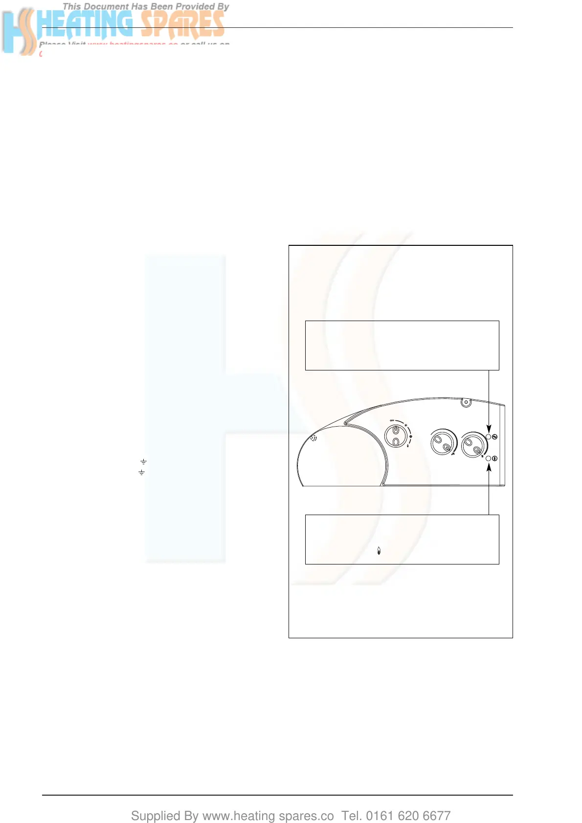
6.5 FAULT FINDING LEDS
The indicator leds signalling irregular and/or incorrect oper-
ation of the equipment are indicated in fig. 26.
Before commencing any service operation, ISOLATE the
mains electrical supply, and TURN OFF the gas supply at the
main service cock. It is the law that any service work must be
carried out by registered personnel (C.O.R.G.I.).
6 FAULT FINDING
Fig. 26
Bi-colour green led off if power is cut-off
Bi-colour orange led: C.H. sensor fault
Bi-colour orange led flashing: insufficient system pressure
Green led flashing: fan/smoke pressure switch failure
Red led on, ignition lock-out/safety and smokes stats
tripped: turn the selector switch briefly to the position
marked ( ) to restore functioning