NOTE:
– The room thermostat must be connected to the terminals 10-11 of the “TA” connector after
having removed the link.
– To remote control the boiler connect an external clock to the terminals 10-11 (24 V) of the
“TA” connector and set the built-in clock to “constant” mode (see user instructions for details).
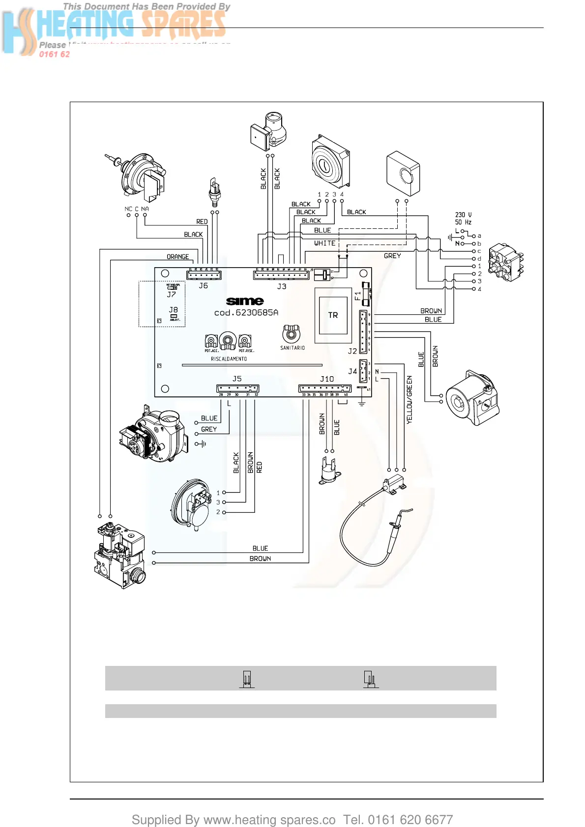
Fig. 27
JUMPERS POSITION AND FEATURES
JUMPER POSITION AND FEATURE SUPPLY POSITION
CLOSED OPEN
J7 - METANO/GPL Ready to function with LPG Ready to function with natural gas Open
J8 - ANN. RIT.* Ignition delay cancelled Ignition delay operating Open
* In the heating phase, the electronic board is programmed to include a burner technical delay interval of approx. 3 minutes, which occurs both
at system cold starting and at subsequent re-ignitions. The aim is to overcome the problem of repeated ignitions and turning off with very short
time intervals between. This could occur in particular in systems presenting high head losses. At each restart after the period of slow ignition,
the boiler will set itself for about 1 minute at the minimum modulation pressure, and will then move to the heating pressure value set.
JUMPERS