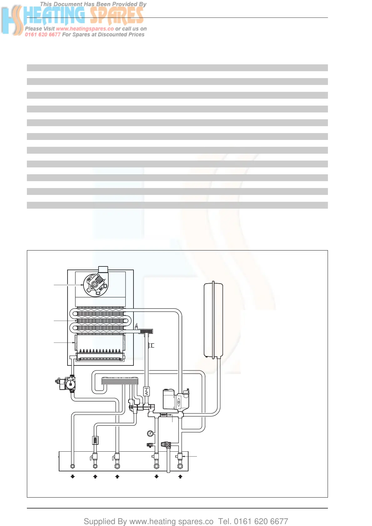
1.4 HYDRAULIC CIRCUIT
KEY
1Fan
2 Water-gas exchanger
3 Combustion chamber
4 Gas valve
5 D.H.W. exchanger
6 Divertor valve
7 NTC sensor
8 100°C safety thermostat
9 Air relief valve
10 Circulation pump
11 Expansion vessel
12 Safety valve
13 Drain plug
14 Water flow switch
16 Automatic by-pass
17 D.H.W. filter
18 C.H. return cock
19 C.H. flow cock
20 D.H.W. cock
21 Gas cock
27 Temperature gauge phial
28 Pressure gauge
29 C.H. water filter
80 C 100 C 110 C
Main burner injectors No off 12 14 15
Dia for Natural gas
mm 1.3 1.3 1.3
Dia for LPG mm 0.77 0.78 0.80
Water capacity l (gal) 3.4 (0.75) 4.7 (1.00) 4.7 (1.00)
Minimum water flow D.H.W. l/min (gal/min) 2 (0.5) 2 (0.5) 2 (0.5)
D.H.W. flow rate
at a temperature rise of 30°C l/min (gal/min) 11.2 (2.5) 13.8 (3.0) 15.1 (3.3)
35°C l/min (gal/min) 9.6 (2.1) 11.9 (2.6) 12.9 (2.8)
Static head Minimum bar (psi) 0.5 (7.3) 0.5 (7.3) 0.5 (7.3)
Maximum bar (psi) 3.0 (43.5) 3.0 (43.5) 3.0 (43.5)
D.H.W. pressure Minimum bar (psi) 1.0 (14.6) 1.0 (14.6) 1.0 (14.6)
Maximum bar (psi) 6.0* (87) 6.0* (87) 6.0* (87)
Weight Empty kg (lb) 38 (84) 40 (88) 40 (88)
Total (full) kg (lb) 41.4 (91) 44.7 (98) 44.7 (98)
Electrical supply 230 V - 50 Hz, Fused at 3 A
Internal fuse Line: F 1.6 A
Maximum power consumption Watt 150 160 160
Maximum gas consumpt. (Natural gas) m
3
/h (ft
3
/h) 2.73 (96) 3.34 (118) 3.68 (130)
Maximum gas consumpt. (Butane - Propane) kg/h (lb/h)
2.02 - 1.99 (4.45 - 4.39) 2.48 - 2.44 (5.47 - 5.38) 2.74 - 2.70 (6.04 - 5.95 )
Max. working temperature °C (F) 95 (203) 95 (203) 95 (203)
Integral exp. vessel capacity l (gal) 8 (1.76) 8 (1.76) 8 (1.76)
* For greater pressures it is necessary to install a pressure reducer in the inlet of D.H.W.
TABLE 4 - General specifications
Fig. 2
DHW MCW GAS FLOW RETURN