23
ENG
FR
3.3 ELECTRONIC IGNITION
Ignition and flame detection is controlled by
an electrode located on the burner. These
guarantee maximum safety with interven-
tion times, for accidental switching off or
gas failure, of within one second.
3.3.1 Operating cycle
Rotate the rotary switch to summer or win-
ter, the red led should light up.
Burner ignition normally takes place within
10 seconds. However, it is possible for igni-
tion failures to occur, with consequent acti-
vation of signal indicating that the control
box has “locked out”.
– Gas failure
The control box runs through the cycle
normally sending electric power to the
ignition electrode. The electrode conti-
nues spark discharge for a maximum of
10 sec. If the burner does not ignite, the
control box “locks out”.
This may occur upon first ignition or
after long periods of boiler lay-off when
there is air in the pipes. It may be caused
by the gas cock being closed or by one of
the valve coils having a break in the win-
ding, so that the valve cannot open.
– Ignition electrode fails to spark
In the boiler, only the gas to the burner is
seen to open. After 10 sec. the control
box “locks out”.
This may be due to a break in the wire of
the electrode or to the wire not properly
fastened to the electric terminal of the
ignition transformer.
The electrode is earthed or very worn
and needs to be substituted. The control
box is defective.
When there is a sudden voltage failure, the
burner shuts out immediately; when power
supply returns, the boiler will start up again
automatically.
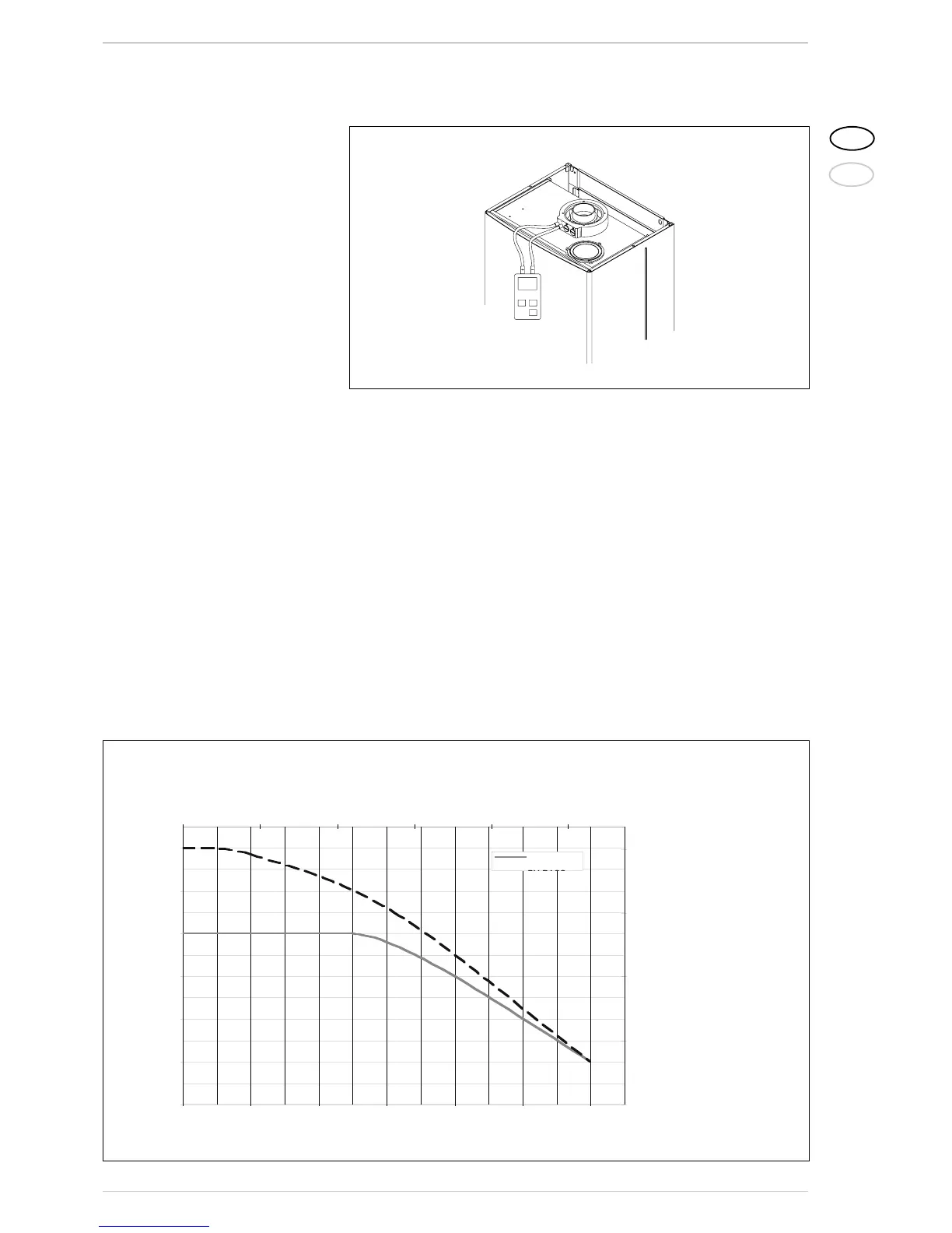
3.4 SMOKE PRESSURE
SWITCH
(fig. 16)
The pressure switch with fixed settings: 4.6-
5.6 mmH
2
O (0.18-O.22 ”W.C.H
2
O), is able to
guarantee the boiler operation even with air
intake and smoke outlet pipes at the maxi-
mum limit of the length allowed.
The value of the signal to the pressure swit-
ch is measured by means of a manometer
connected as shown in fig. 16.
3.5 FLOW SWITCH SAFETY VALVE
The flow switch (8 fig. 5) is tripped and
stops the burner when it does not detect
water flow in the primary circuit > 400
l/h (1.76 USgpm).
To restore burner func-
tioning, check system pressure and the
functioning of the pump and the flow swit-
ch, and the cleaning of the “Aqua Guard Fil-
ter System” filter.
NOTE: If replacing the flow switch valve,
make sure that the arrow stamped on the
valve points in the same direction as the
flow of water.
3.6 HEAD AVAILABLE TO SYSTEM
Residual head for the heating system is
shown as a function of rate of flow in the
graph in fig. 17.
To obtain the maximum head available to
Figure 16