25
ENG
FR
4.1 D.H.W. TEMPERATURE
ADJUSTMENT
The system with a potentiometer for adju-
sting the temperature of D.H.W. with a set-
ting range from 30° to 60°C (86-140 °F)
offers a double advantage:
1) The boiler adapts perfectly to any type of
D.H.W. system, whether the mixing
system is a mechanical or a thermostat-
controlled type.
2) The thermal output is dosed according
to the temperature required, which
means a considerable saving in fuel.
NOTE: In order to avoid any misunderstan-
ding please remember that the value obtai-
ned by the product of temperature differen-
ce (in °C) between D.H.W. output and input
into the boiler by the hourly flow rate measu-
red on the tap, where hot water is drawn off
(l/h), cannot be higher than the useful output
developed by the boiler.
For measurements and checks on flow rate
and temperature of D.H.W., use suitable
instruments, taking into consideration any
heat dispersion along the stretch of piping
between the boiler and the measuring point.
4.2 ADJUSTMENT OF
D.H.W. FLOW RATE
To adjust the D.H.W. flow rate, use the flow
rate adjuster (5 fig. 5).
Remember that the flow rates and corre-
sponding temperatures of use of hot water
have been obtained by positioning the selec-
tor of the circulation pump on the maximum
value.
Should there be any reduction in the
D.H.W. flow rate, the filter installed on the
inlet to the divertor valve (3 fig. 5) will
need cleaning.
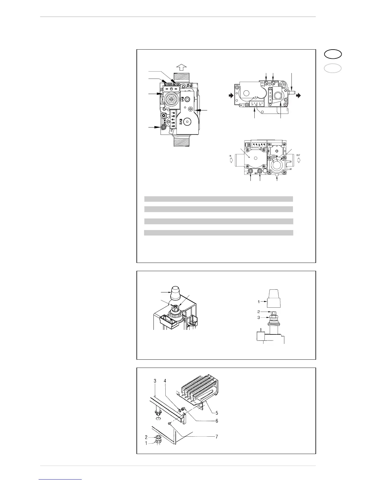
4.3 GAS VALVE
The boilers are equipped standard with the
SIT 845 SIGMA/HONEYWELL VK 4105M
/SIEMENS VGU 50 gas valve (fig. 21).
The gas valve is set at two pressure values:
maximum and minimum. According to the
type of gas burnt, these correspond to the
values given in Table 4.
The gas pressures at the maximum and
minimum values, are factory set. Conse-
quently they must not be altered. Only when
you switch the appliance from one type of
gas supply (methane) to another (propane),
it is permitted to alter the operating pres-
sure.
4.4 GAS CONVERSION
This operation must be performed by
authorised personnel using original Sime
components.
To convert from natural gas
to LPG or vice versa, perform the following
operations (fig. 22):