1-3
CITY1/DACT CITY2
TP3
TP1
TP2
P5
P6
P4
K1
U33
R95
WARM START
EXT RUI DET PWR
INT RUI
RS-232 PORT
1234
ASSY 0565-473 4 POINT IDC
TB1
**SYSTEM IS NORMAL**
12:02:15PM AUG 10, 1995
ALARM
ACK
SUPV
ACK
TROUBLE
ACK
ALARM
SILENCE
SYSTEM
RESET
FIRE
ALARM
SYSTEM
SUPERVISORY
SYSTEM
TROUBLE
ALARM
SILENCED
AC
POWER
P2
P1
SW2
R83
TB1
TB2
AC Line AC Ret Earth
115V
NEG POS
P3
T1
F1 3A
JW1
R69
SW1
ASSY 0565-473 4 POINT IDC
TB1
NAC/RELAY ASSY565-477
TB1
J1
F1
F2
F3
F4
3A
3A
3A
3A
K1
K2
K3
K4
Optional I/O Card
Optional I/O Card
Optional I/O Card
Optional I/O Card
Optional I/O Card
Optional City/DACT Optional City Card 2
Card 1
Battery (18Ah Max.) Battery (18Ah Max.)
Optional I/O Card
Optional I/O Card
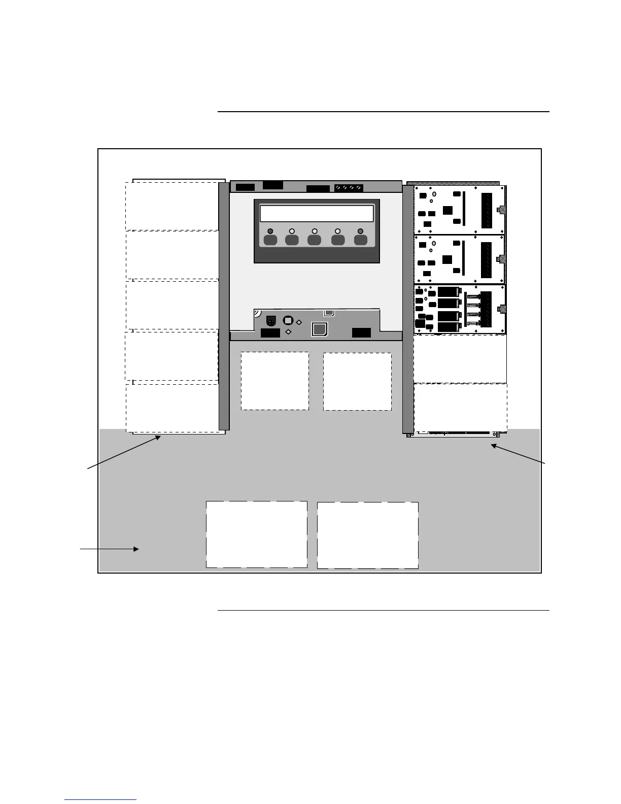
Figure 1-1. 4005 Base Panel Card layout
Continued on next page
Description and Features, Continued
Description (continued)
Non-Power-
Limited
Wirin
Optional
Expansion
Power Supply
(Behind I/O
Cards)
Power
Supply
(Behind
I/O Cards)
Technical Manuals Online! - http://www.tech-man.com