Page 39 579-1102 Rev H
4007ES and 4007ES Hybrid Fire Alarm Systems Installation Manual
8 Appendix A ULC programming requirements
8.1 Common earth fault ground and common trouble indicator
This application monitors a system pseudo that counts the number of ground faults or troubles that occur on the system. Each time this counter
increments, such as when a ground fault or trouble occurs, a yellow LED on the operator interface panel illuminates.
Step 1. Add a Custom Control equation to monitor all ground faults:
1. Click the Custom Control tab.
2. Add a new equation.
3. Paste the following equation:
[INPUTS]
STATUS ON
A112 | ANALOG | COUNTER | GROUND TROUBLE COUNTER
OR STATUS ON
2-0-8 | CARDSTAT | CSP | IDNET+ EARTH TROUBLE
[END INPUTS]
[OUTPUTS]
TRACK ON PRI=9,9
P535 | DIGITAL | UTILITY |
[END OUTPUTS]
NOTE: P535 is shown as an example; use any digital point.
Step 2. Open Color User Interface Card Properties Dialog
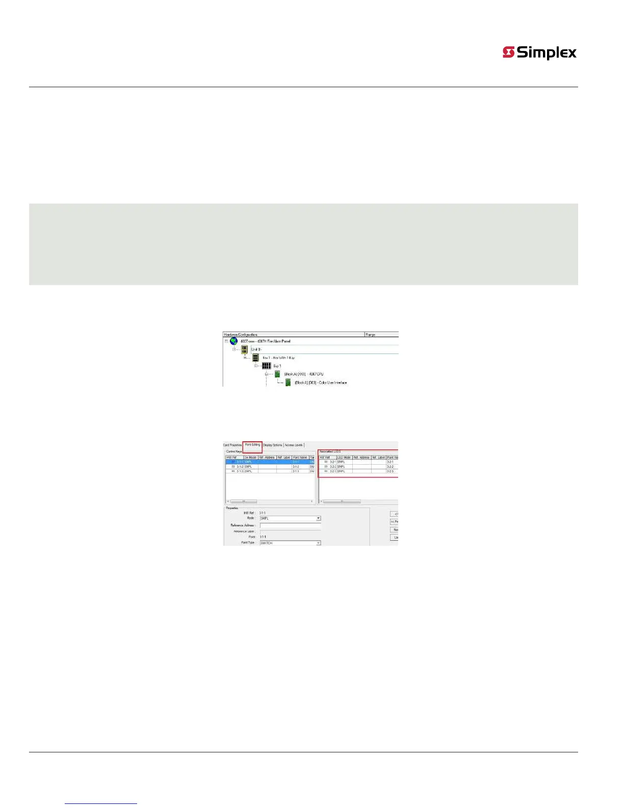
1. Click the Hardware tab and expand the Unit 0, Box 1, Bay 1 icons to display the Color User Interface Card. Click the + signs to the left of the
Unit 0, Box 1, and Bay 1 icons to expand them.
Fig 35: Selecting the Color User Interface
Card
2. Right-click the Color User Interface card icon and select Properties.
3. Click the Point Editing tab, see Figure 36: The Display tab:Display Checkboxes on page 39.
Fig 36: The Display tab:Display Checkboxes
Step 3. Program the LED
1. Select one of the multicolor LEDs (3-2-1, 3-2-2, or 3-2-3) to program.
2. Click the Point Type drop down list and select LEDYELLOW.
3. Click the Mode drop down list and select ON.
4. Enter P535, or your chosen digital point number from the equation, in the Reference Address field to program the LED for ground faults.
OR
5. Enter A2 (no spaces) in the Reference Address field to program the LED to illuminate whenever a general system trouble is present.

 Loading...