EasyManuals Logo

Simplex 4020 Troubleshooting Guide

Simplex 4020
34 pages
To Next Page IconTo Next Page
To Previous Page IconTo Previous Page
Page #15 background imageLoading...
Page #15 background image
2-10
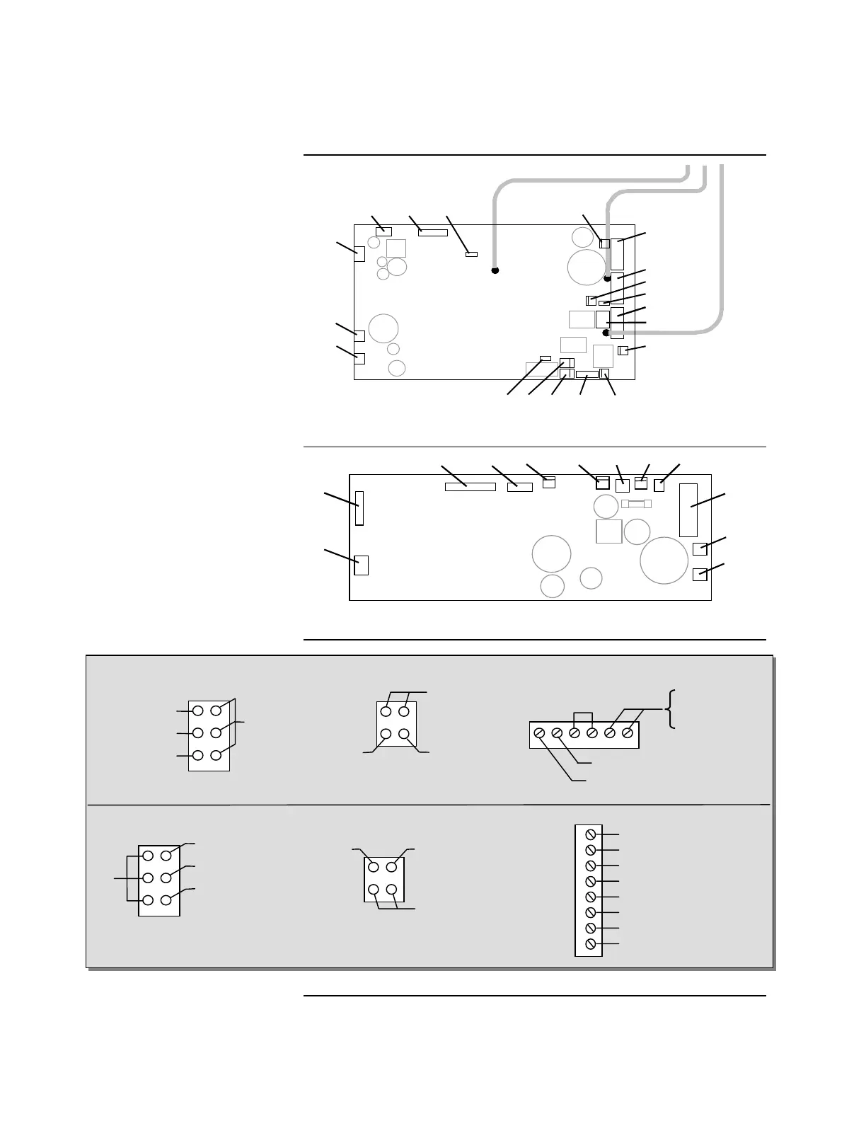
Figure 2-5. 565-256 Power I/O Interface PCB Assembly
Figure 2-6. 565-220 Power I/O Interface PCB Assembly
Figure 2-7. Voltage Points on Power I/O PCB Connectors and Terminal Blocks
Continued on next page
4020 Power I/O Interface,
Continued
Power I/O Interface PCB
Layout
P4
J1
P12
TB2
TB3
P10
P13
TB4
P14
P11
RED
BLK
YEL
R139
P1
P2
J1
J2
P3
P4
P5
P6
P7
TB1
P8
P9
+ 24 V A-tap ( TB2 )
+ 24 V B-tap ( TB3 )
+ 24 V C-tap ( TB4 )
565-256 TB2, TB3 or TB4 Terminal Block565-256 P2 or P3 Connector
565-220 P8 or P9 Connector
565-220 TB1 Terminal Block
565-256 P4 Connector
0 V
+ 24 V (System)
+ 5 V (Std Slaves)
0 V
3 6
2 5
1 4
565-220 P2 Connector
0 V
+ 24 V (System)
+ 5 V (Std Slaves)
0 V
4 1
5 2
6 3
Trouble
(Low = Trouble)
+ 36 V
(Mapnet)
0 V
4 3
2 1
Trouble
(Low = Trouble)
+ 36 V
(Mapnet)
0 V
1 2
3 4
B– Return
B+ Return
0 V B
+24 V B-tap
A– Return
A+ Return
0 V A
+24 V A-tap
8
7
6
5
4
3
2
1
0 V
6 5 4 3 2 1
+ Return
– Ret
urn

Table of Contents

Other manuals for Simplex 4020

Questions and Answers:

Question and Answer IconNeed help?

Do you have a question about the Simplex 4020 and is the answer not in the manual?

Simplex 4020 Specifications

General IconGeneral
TypeFire Alarm Control Panel
ManufacturerSimplex
Model4020
DisplayLCD
Frequency50/60 Hz
Battery BackupYes
NAC Outputs4
Power120/240 VAC
Voltage120/240 VAC
Operating Temperature0°C to 49°C (32°F to 120°F)
Humidity RangeUp to 93% RH, non-condensing
Communication ProtocolOptional

Related product manuals