5-1
The following sequence is documented F
OR
R
EFERENCE
O
NLY
.
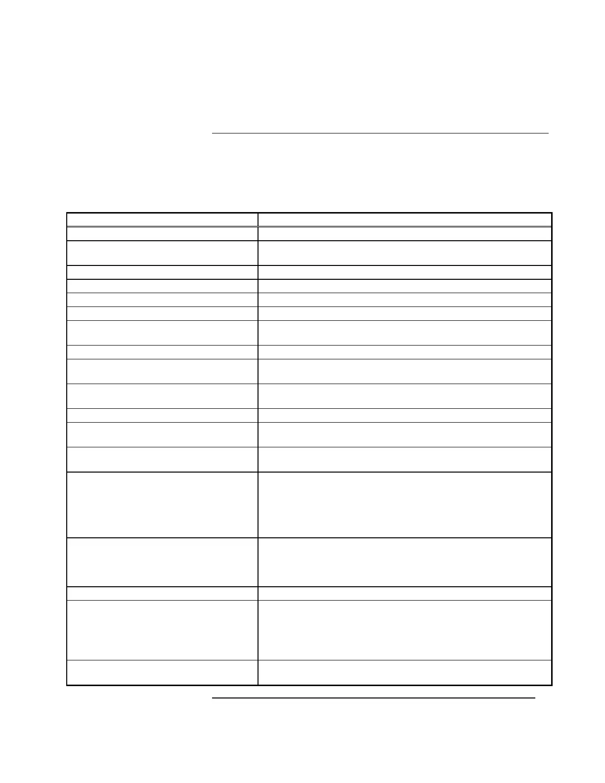
On start-up, the 4020 Standard Slave Card performs the checks shown in Table 5-1.
Table 5-1. Standard Slave Initialization Sequence
Card Operation Description and Remarks
1. Check for warm or cold start -----
2. Perform micro set-up routines (ports,
etc.)
-----
3. Sets PCC reset low; trouble LED on Start PCC reset
4. Test PROM checksum Bad checksum will hang system at this step
5. Set PCC reset high Complete PCC reset
6. Check internal and external RAM Bad RAM will hang system here
7. Check address DIP switch Address must be less than 118; card hangs if it is >117 (Usual
setting: 1-7 on, 8 off)
8. Set internal address & baud rate -----
9. Check power supply set-up switch
and set bits to be used later
-----
10. Begin initializing cards, starting with
power supply
-----
11. Check AC power Green LED on interface will be
ON
if the AC power is good.
12. Read main voltage (A/D) Sets a “voltage good” bit if in desired range (25V-31V) through
the A/D converter on the Power I/O Interface board.
13. Read battery voltage (A/D) Sets a “voltage good” bit if > 19.5V through the A/D converter on
the Power I/O Interface board.
14. If cold start:
• AC good = run on AC
• AC bad, Battery good = run on
battery
• AC bad, Battery bad = restart
Bad AC and Battery voltages at this point will hang the system.
Main voltage at red and black wires should be approximately
28.5V and green LED on power supply interface should be
ON
15. If Warm Start:
• AC good = run on AC
• AC bad = run on batteries
Bad AC and Battery voltages at this point will hang the system.
Main voltage at red and black wires should be approximately
28.5V and green LED on power supply interface should be
ON
16. Set taps off to be sure they are off -----
17. Read current on A, B & C-taps via
the A/D converter
All readings should be zero; if not, processor will loop and keep
checking (could hang.)
If hung, this could be a problem with the A/D or the cable to the
Power I/O. All taps will be off; Green LED on PS interface will
be
ON
18. Check to see if the charger is
enabled (PS setup switch.)
-----
Continued on next page
Chapter 5
Standard Slave Software Initialization
Standard Slave Initialization
Sequence