5-2
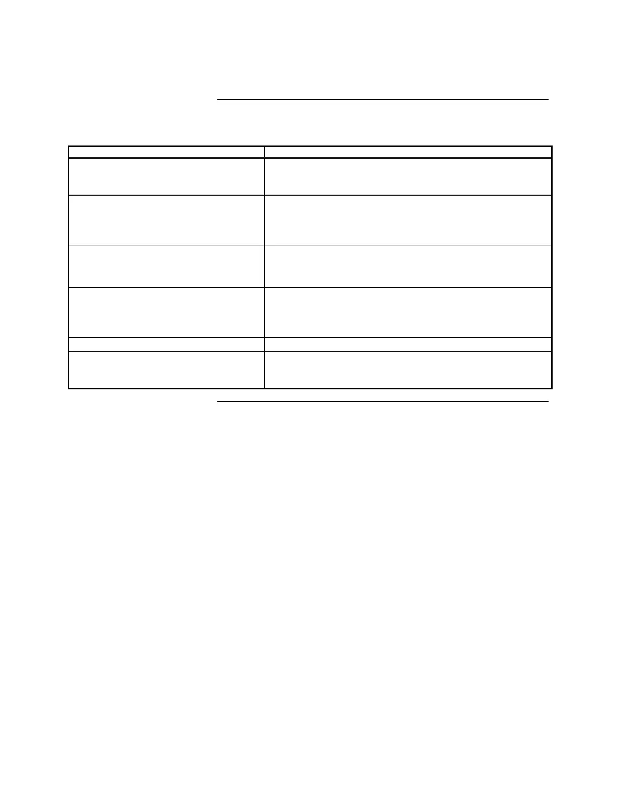
Table 5-1. Standard Slave Initialization Sequence
(continued)
Card Operation Remarks
19. Turn on taps If there is 28.5V at the A & B Taps, 27.6V at C (If charger is
enabled) this indicates the software completed the preceding
steps.
20. If charger not enabled, turn off C-tap. At Switch SW2.
(If you set SW2 position 3 and 4 closed on Standard Slave
and restart -- If software is working, A & B tap will come up,
C will not.
21. Initialize Mapnet circuitry:
• Internal setups
• Reset PCC, etc.
-----
22. Turn on Mapnet voltage Picks K2 on Standard Slave
(+36V across Mapnet output terminals indicates Power
Supply, Power Supply I/O Interface and Interface A/D are
probably OK.)
23. Initialize I/O cards Check and set up I/O parameters
24. Begin communicating with Master
Controller.
If +36V exists at Mapnet and there is no communication, the
problem is communications related. Check addresses,
communication circuit & harnesses
Standard Slave Software Operation,
Continued