Note:
1. If the 2098-9808 Remote LED or 4098-9822 relay is used, the remote LED and relay wires are not supervised.
2. The maximum quantity of devices on a circuit is 127 for 4020, 4100+, 4100U/4100ES/4010ES (MAPNET), or 4120, 128 for the
2120 CDT panel, 200 for the 4008 panel, and 250 for the 4010 and 4100U/4100ES/4010ES/4007ES (IDNET) panel.
3. If a shield is used, twist the shield wires together and cap with a wire nut. Insulate the shield from the electrical box.
4. Contact A or B: Dry, Form C - each rated 2 A at 24 VDC / 0.5 A at 110 VAC, resistive.
5. 18 to 32 VDC, 0.008 A typical / 0.013 A max.
6. Do not use a remote LED if the 4098-9822 relay module is used.
7. Contact A or B: Dry, Form C - each rated at 3 A at 28 VDC / 115 VAC, resistive.
8. Remove the protective tape over the CO Sensor on the 4098-9770, 4098-9771, 4098-9773 bases only after the sensor head has
been installed.
9. The maximum wire length between 4098-9791 sensor base and 2098-9737 relay module is 100 feet, or 30.48 meters.
10. The maximum quantity of sensors with 4098-9771, 4098-9772, 4098-9773, 4098-9794, and 4098-9798 sounder bases is limited
to 43 if output is coded, Temporal code, and so on, using MAPNET II/IDNet control. If coding is performed using a 24 VDC or NAC
circuit, see note 2.
11. When 4090-9116, 4098-9777, or 4098-9793 isolators are present on the channel, the maximum line resistance between the
panel and the isolator, or between two isolators is 10 ohms, 780 feet, or 237.74 meters at 18 AWG.
12. Contacts Dry Form C, rated at 2 A at 30 VDC / 0.5 A at 125 VAC, resistive.
13. The maximum wire length between 4098-9780 sensor base and 4098-9860 relay module is 100 feet, or 30.48 meters.
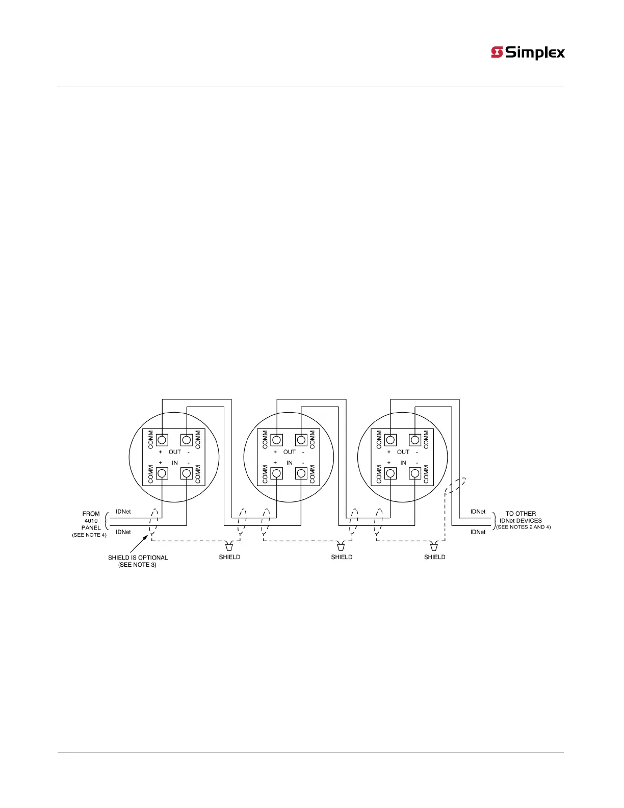
Figure 15 shows the wiring connections for the isolator sensor base. All screw terminals accept 14 to 18-gauge AWG solid or stranded wire.
Ensure the maximum torque does not exceed 12-inch-pounds.
CAUTION: Do not loop the wire under the terminals. Break wire runs to provide supervision.
Figure 15: 4098-9793, 4098-9777, 4098-9766, 4098-9767 Isolator Sensor Base connections
Note:
1. The isolator bases 4098-9777 and 4098-9793 are compatible with the 4010, 4100U, 4100ES, 4010ES, 4007ES, or 4008 panel
ONLY.
2. The maximum quantity of devices on a circuit is 250 for 4010, 4100U, 4100ES, 4010ES, and 4007ES panels.
3. If shield is used, twist the shield wires together and cap with a wire nut. Insulate the shield from electrical box.
4. When 4090-9116, 4098-9777, or 4098-9793 isolators are present on the channel, the maximum line resistance between the
panel and the isolator, or between two isolators is 10 ohms (780 feet, or 237.74 meters at 18 AWG).
5. The Isolator2 bases 4098-9766 and 4098-9767 are compatible with the 4100ES, 4010ES, or 4007ES providing IDNet2 only.
6. For more detailed information about the use of IDNet Isolator2 bases (4098-9766, 4098-9767) refer to Isolator2 Usage Guidelines
(579-1313).
7. When Isolator2 (4090-9122, 4098-9766, or 4098-9767) are present on the channel, the maximum number of isolators
(4090-9116, 4090-9122, 4098-9766, 4098-9767, 4098-9777, or 4098-9793) is 50.
page 26 574-709 Rev. AP
4098 Detectors, Sensors, and Bases Application Manual