Installaon — 15
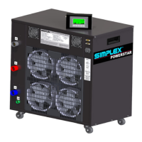
1. To bring in the source’s
power cables, cut holes in
the Conduit Opening, lo-
cated in the bottom of the
load bank’s control panel
enclosure (see Figure 5
Conduit Opening).
2. Conrm the test source is
properly grounded.
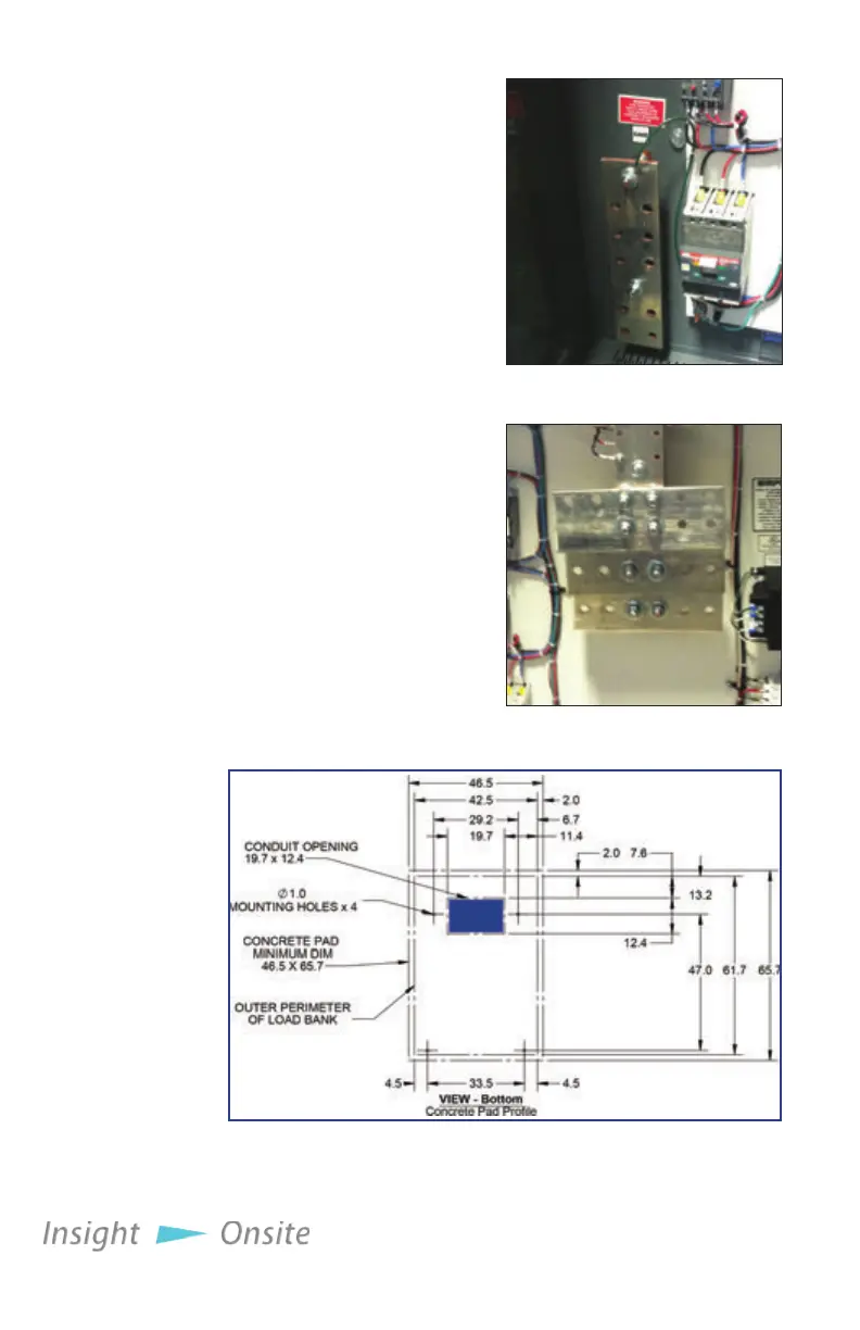
3. Ground the load bank by
connecting the Ground-
ing Bus to an earth
ground or grounding rod.
See Figure 3 Ground Bus
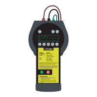
4. Connect the source’s
power output to the load
bank via the Main Load
Bus with appropriately
sized cables (see Figure 4
Main Load Bus).
inStallation
p
roCedure
Neptune load
banks feature
a power
outlet in the
control panel
for your use.
This outlet is
limited to 2
amps.
Figure 3 Ground Bus
Figure 4 Main Load Bus
Figure 5 Conduit Opening