Steering Gear Adjustment
If there is excessive slack in the steering system, the
steering gear backlash can be removed.
1. Locate the steering gear assembly on the underside
of the tractor (see Figure 22). Loosen the two nuts
and adjust the bracket so the gear teeth are closely
meshed.
2. Tighten nuts (A) to 36-44 ft-lbs (49-59 Nm) after
adjustment.
Brake Adjustment
1. Disengage the PTO, stop the engine, block the
wheels, remove the ignition key, and engage the
parking brake.
2. Remove the mower deck (see Mower Deck
Removal).
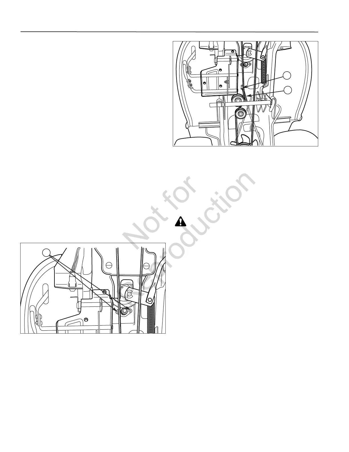
3. Locate the brake spring (A, Figure 23) and
adjustment nut (B).
4. With the parking brake engaged, measure the
compressed spring length. The spring should be 2-
1/2” (6,4 cm) when compressed.
If the spring is not within this range, turn the
adjustment nut to compress or release the spring.
If this adjustment does not correct a braking problem,
see your dealer.
Figure 22. Steering Gear Adjustment (Manual
Steering Only)
Figure 23. Brake Spring Adjustment
A
B
A
WARNING
To avoid serious injury, perform adjustments only
with engine stopped, key removed and tractor on
level ground.
30
TROUBLESHOOTING
PTO Clutch Adjustment
Check the PTO clutch adjustment after every 250 hours
of operation. Also perform the following procedure if the
clutch is slipping or will not engage, or if a new clutch
has been installed.
1. Remove key from ignition switch and disconnect
spark plug wires to prevent the possibility of
accidental starting while the PTO is being adjusted.
2. Note the position of the three adjustment windows (A,
Figure 24) in the side of the brake plate and the
nylock adjustment nuts (B).
3. Insert a .012”-.015” (2,5-4 mm) feeler gauge (A,
Figure 25) through each window, positioning the
gauge between the rotor face and the armature face
(B) as shown.
4. Alternately tighten the adjustment nuts (C) until the
rotor face and armature face just contacts the gauge.