9 - 5
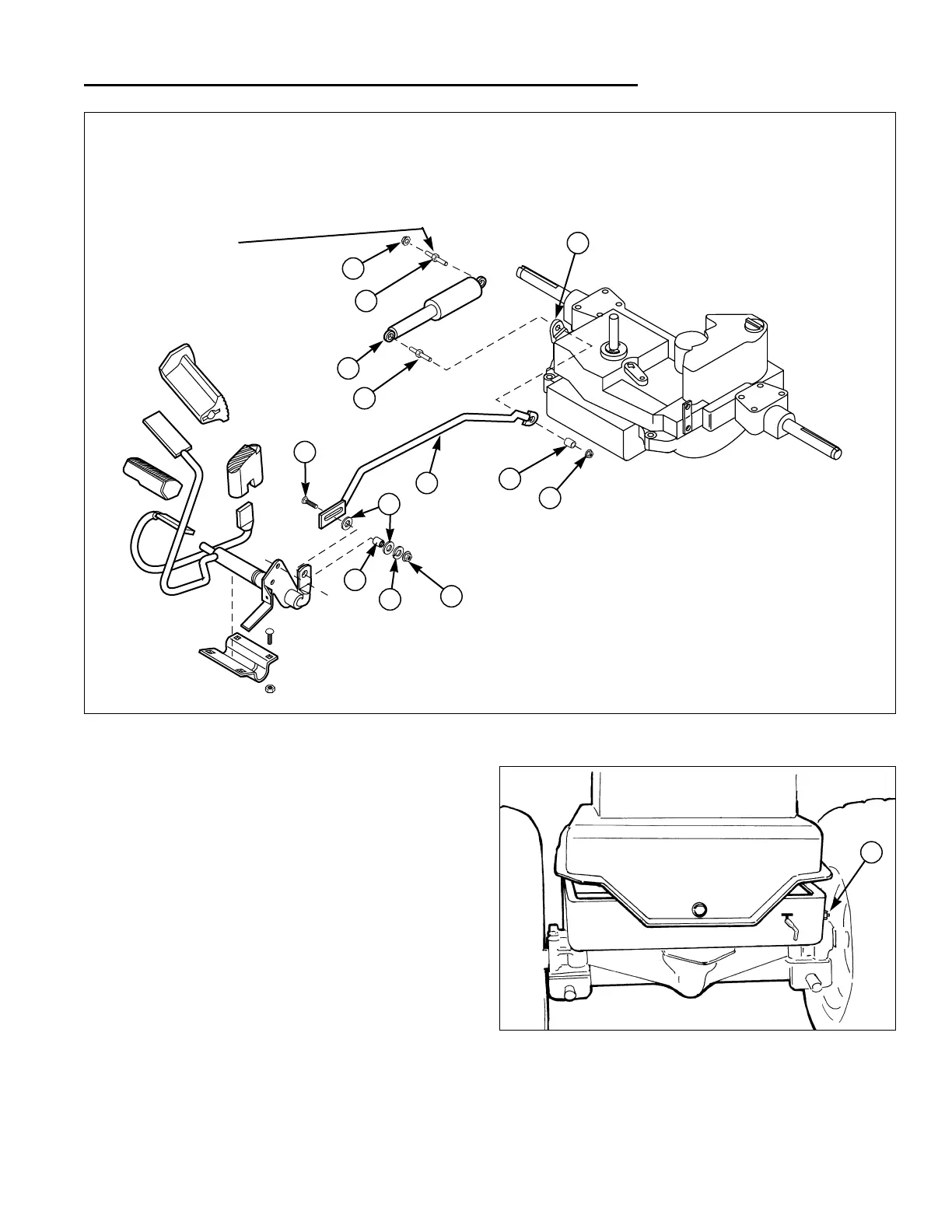
Transmission Control Rod and
Shock Absorber Removal & Installation
1. Remove the nut (L, Figure 4) and carriage bolt (H)
securing the front of the transmission control rod (D)
to the foot pedal arm.
2. Remove the locknut (G, Figure 4) and spacer (F)
from the stud (B).
3. Locate the nut on the right rear corner of carrier
assembly (A, Figure 5).
4. Remove nut (A, Figure 4) and stud (B).
5. Remove the shock absorber (C, Figure 4).
Install in reverse order of removal. After installation per-
form GROUND SPEED CONTROL FOOT PEDAL
ADJUSTMENT procedure found in Section 4.
9 Drive Controls Service
Tuff Torq K-56 Models
Figure 4. Transmission Control Linkage
A. Nut
B. Stud
C. Shock Absorber
D. Trans. Control Rod
E. Trans. Control Lever
F. Spacer
G. Locknut
H. Carriage Bolt
I. Washers
J. Spacer
K. Lockwasher
L. Hex Nut
A
H
J
K
L
B
B
C
E
F
G
D
I
Mounts in Right
Rear Corner of
Carrier Assembly
Figure 5. Shock Absorber Stud Location
A. Shock Absorber Stud
A
Transmission Control Linkage -
Tuff Torq K-56 Models

 Loading...