11 - 13
11 Transmission Teardown
Hydro-Gear 0500 / 0650
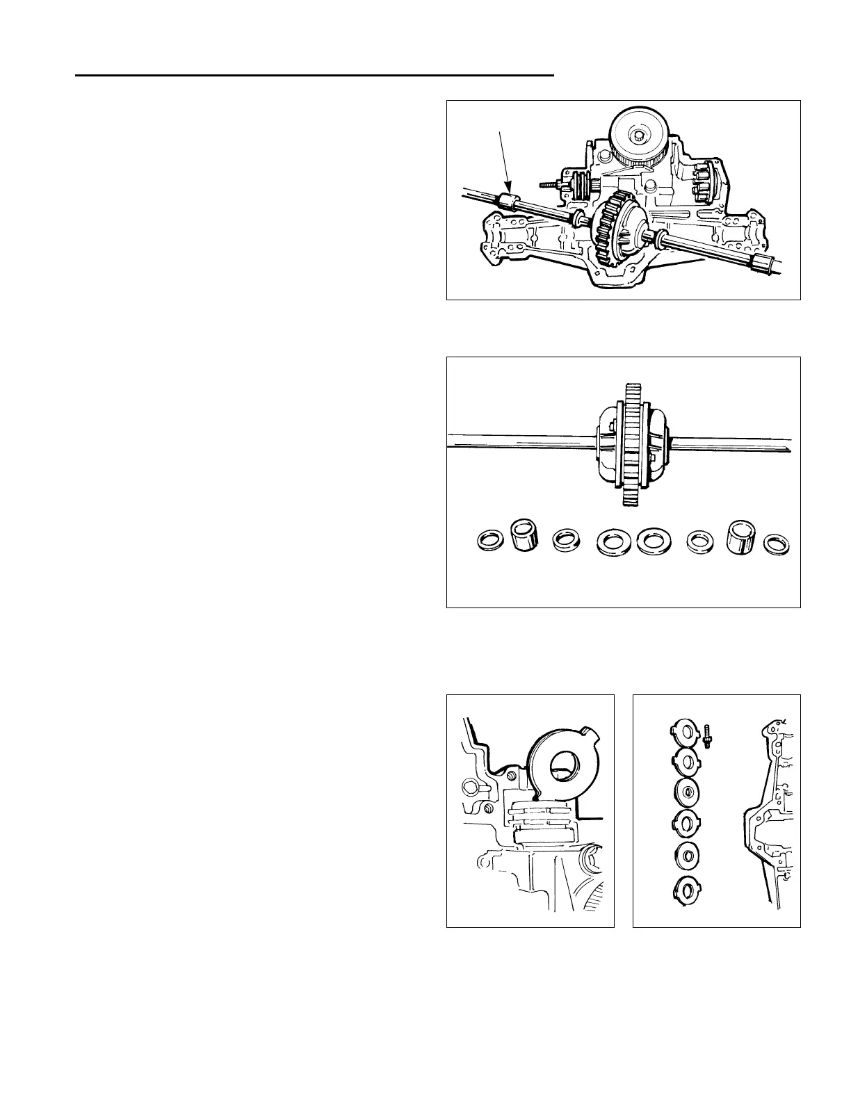
Figure 9. Remove Axle / Differential Assembly
10.Inspect the bronze bearings for excessive wear. The
bearings should be 0.754” to 0.756”.
11.Inspect the axle ends for damage or excessive wear.
The axle ends should be 0.749” to 0.750”.
Figure 10. Axle / Differential Components
12.Inspect the differential bevel gears by rotating the
axle ends.
13.Inspect the final drive gear teeth for excessive wear
or damage.
14.Check the differential assembly screws for proper
torque. They should be torqued to 16-18 ft. lbs.
15.Inspect the journal bearings inside the differential
housing for excessive wear by feeling the shafts for
an unreasonable amount of play.
16.If excessive wear or damage has been found, the
complete assembly must be replaced.
Journal Bushing
Figure 11. Remove / Inspect Brake Rotors
17.Remove the brake rotors and stators by sliding one at
a time off the end of the splined motor shaft.
18.Inspect each side of both rotors for excessive wear or
damage.
19.Inspect the rotor’s internal splines for excessive wear
or damage.
20.Replace rotors and stators as a complete kit if exces-
sive wear or damage is found. Inspect all other mating
parts.
 Loading...