GD1 Page 22 of 76 850-816926-EN R06
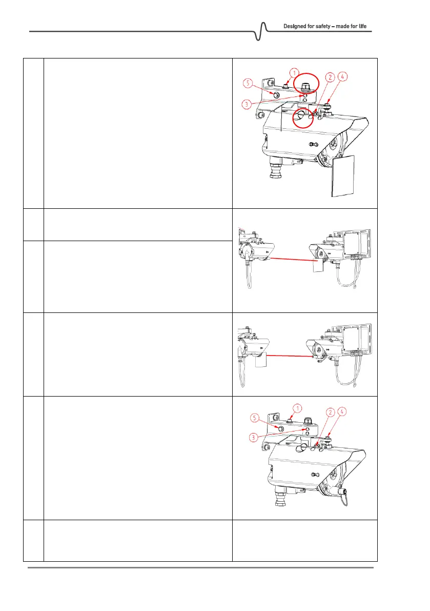
Loosen screws 2 and 3 on both the TX and RX.
Important: Nut A and nut on bolt B are
tightened correctly in the factory and should
not be touched. If tightened too much, they
may jeopardize the correct operation of
adjustment screws.
Rotate horizontally by hand so the RX and TX
points towards each other.
Adjust the RX with screws 4 (vertical direction)
and horizontal by hand until the laser spot hits
the target plate on the TX.
Tighten screws 2 and 3 fully on RX so it cannot
be moved by hand anymore.
Swap sides Alignment Laser and Laser Target
Plate so Alignment Laser now is attached to
the TX side.
Now adjust the TX with screws 4 (vertical
direction) and horizontal by hand until the
laser spot hits the target plate on the RX.
Tighten screws 2 and 3 fully on TX so it cannot
be moved by hand anymore.
Keep the Alignment Laser and Laser Target
Plate in place to assist in the Fine tuning
procedure.
Coarse alignment finished!