The area in which the detector may be installed must be in accordance
with the certification of the detector and in accordance with the
standards of the appropriate authority in the country of installation.
2.1. System parts
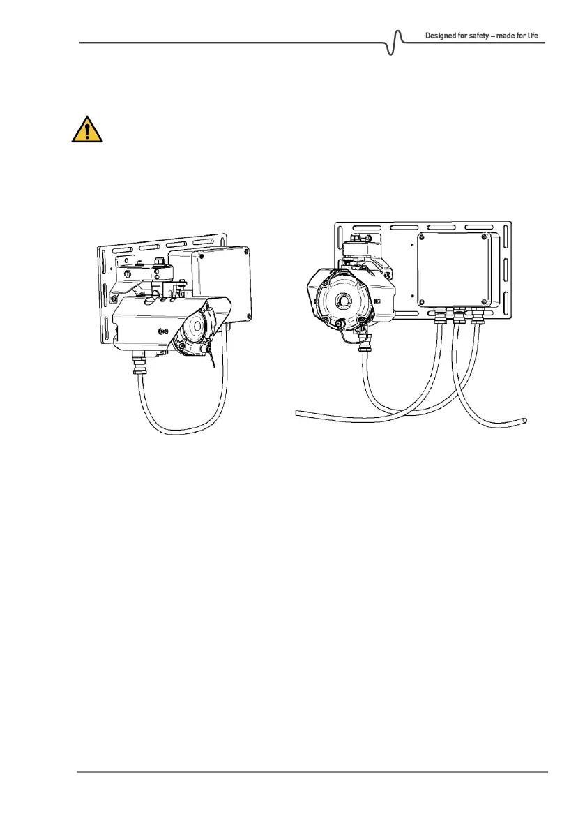
RECEIVER TRANSMITTER
The complete GD1 system consists of a TX sending a laser beam to the RX. Communication
to control room and power to the GD1 is connected to the TX. Between the TX and RX
there is a cable with communication and power.
The TX where the laser is located sends a diffused light beam (invisible) to the receiver. The
beam is shaped as a cone, not a focused laser beam as you might expect from a laser
pointer. The TX comes complete with the TX and junction box mounted on a backing plate.
The RX has a larger optical aperture to collect the transmitted light and add margin to path
alignment. The TX and RX communicate on a data link (cable). The RX comes complete with
the RX and junction box mounted on a backing plate.