BG
BH
BJ
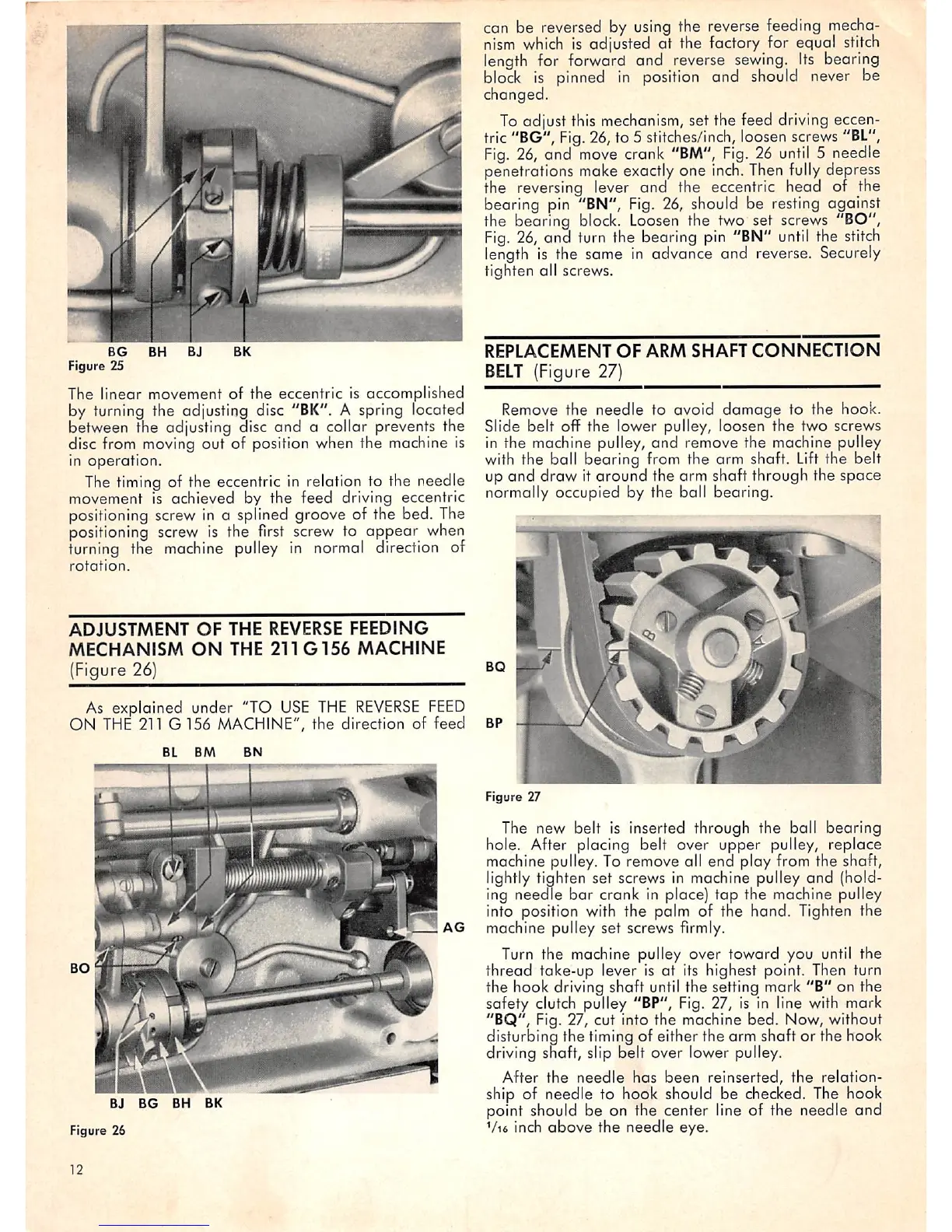
Figure 25
The linear movement of the eccentric is accomplished
by turning the adjusting disc
"BK".
A spring located
between the adjusting disc and a collar prevents the
disc from moving out of position when the machine is
in
operation.
The
timing
of the eccentric in relation to the needle
movement is achieved by the feed driving eccentric
positioning screw
In
a splined groove of the bed. The
positioning screw is the
first
screw to appear when
turning
the
machine
pulley
In
normal
direction of
rotation.
ADJUSTMENT
OF
THE
REVERSE
FEEDING
MECHANISM
ON
THE
211G156
MACHINE
(Figure 26)
As explained under "TO
USE
THE
REVERSE
FEED
ON
THE
211 G 156 MACHINE", the direction of feed
BJ
BG
BH BK
Figure 26
12
AG
can be reversed by
using
the reverse feeding
mecha
nism
which
is
adjusted at the factory for equal
stitch
length
for
forward
and
reverse
sewing.
Its
bearing
block
is pinned
in
position and should never be
changed.
To
adjust this mechanism, set the feed driving eccen
tric "BG",
Fig.
26, to 5 stitches/inch, loosen screws
"BL",
Fig.
26,
and
move
crank
"BM",
Fig.
26
until
5 needle
penetrations make exactly one
inch.
Then
fully
depress
the reversing lever and the eccentric head of the
bearing pin "BN",
Fig.
26, should be resting against
the bearing block.
Loosen
the two set screws "BO",
Fig.
26,
and turn the bearing
pin
"BN"
until
the
stitch
length
is the same in advance and reverse.
Securely
tighten all screws.
REPLACEMENT
OF
ARM
SHAFT
CONNECTION
BELT
(Figure
27)
Remove the needle to ovoid
damage
to the hook.
Slide belt off the lower pulley, loosen the two screws
in the machine pulley,
and
remove the machine pulley
with the ball bearing from the arm shaft.
Lift
the belt
up
and
draw it around the arm shaft through the
space
normally occupied by the ball bearing.
BQ
O
BP
Figure
27
The new belt is inserted through the boll bearing
hole. After placing belt over upper pulley, replace
machine pulley. To remove all end play from the shaft,
lightly tighten set screws in machine pulley and (hold
ing needle
bar
crank in place)
tap
the machine pulley
into position with the palm of the hand. Tighten the
machine pulley set screws firmly.
Turn the machine pulley over
toward
you until the
thread take-up lever is at its highest point. Then turn
the hook driving shaft until the setting mark "B" on the
safety
clutch
pulley "BP", Fig. 27, is in line with mark
"BQ", Fig. 27, cut into the machine bed. Now, without
disturbing the timing of either the arm shaft or the hook
driving shaft, slip belt over lower pulley.
After
the
needle
has
been
reinserted,
the
relation
ship of needle to hook should be checked. The hook
point should be on the center line of the needle and
Vi6
inch
above
the
needle
eye.
 Loading...