REGULATION
OF
PRESSER
FOOT
PRESSURE
(Figure 3)
The
pressure on the material should be as light as
possible while
still
sufficient to insure correct feeding.
The presser foot pressure is adjusted with screw
"AE", Fig. 3. Turning of the screw clockwise increases
and
counter-clockwise
decreases
the pressure.
REENGAGEMENT
OF
SAFETY
CLUTCH
(Figure 13)
A safety clutch to prevent any overload
and
damage
to the hook is installed in the lower belt pulley. If it is
disengaged, open the bed slide
and
check the hook.
Remove all thread
and
foreign matter from the hook
by carefully turning the machine pulley forward and
backward until the machine turns freely. Bypressing the
stitch
length
regulator
button
"AD",
Fig.
13,
and at the
same time turning the machine pulley,the hook driving
shaft is locked
until
the safety clutch isreengaged. Reset
the
stitch
length
and the
machine
is ready for
sewing.
TO
USE THE REVERSE FEED
ON
THE
2110156
MACHINE
(Figures
20 and
26)
The feed of the machine can be reversed by hand
lever
or
foot
treadle.
To change feed direction by hand, push the reverse
lever "AF",
Fig.
20, completely down in order to have
the same stitch length as in forward feed.
Release it only when you want to again feed the
material
in
the
normal
direction.
To reverse the
feed
with the foot
treadle,
the
foot
treadle
chain
should
be
connected
to
the
hole
in
the
reversing lever "AG", Fig. 26.
TIMING
AND
OTHER
ADJUSTMENTS
The instructions on the following pages are for Adjusters and Mechanics only.
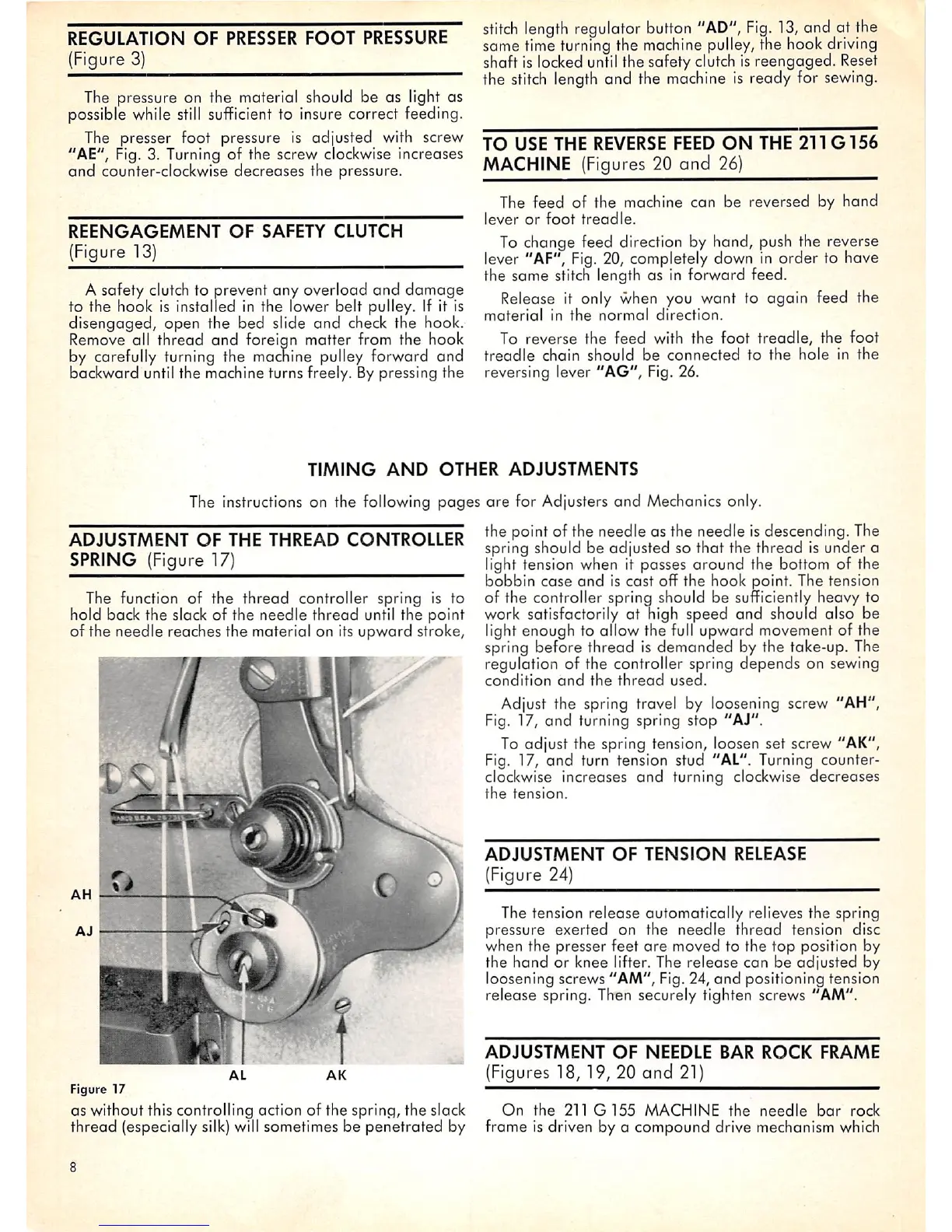
ADJUSTMENT
OF
THE
THREAD
CONTROLLER
SPRING (Figure 17)
The function of the
thread
controller spring is to
hold back the slack of the
needle
thread
until the point
of the needle reaches the material on its upward stroke.
AL
AK
Figure 17
as without this controlling action of the spring, the slack
thread
(especially silk) will sometimes be
penetrated
by
the point of the needle as the needle is descending. The
spring should be adjusted so that the thread
Is
under a
light tension when It passes around the bottom of the
bobbin
case
and
is
cast
off the hook point. The tension
of the controller spring should be sufficiently heavy to
work satisfactorily at high speed and should also be
light enough to allow the full upward movement of the
spring before thread is demanded by the take-up. The
regulation of the controller spring depends on sewing
condition
and
the
thread
used.
Adjust the spring travel by loosening screw "AH",
Fig. 17,
and
turning spring stop "AJ".
To adjust the spring tension, loosen set screw "AK",
Fig. 17,
and
turn tension stud "AL". Turning counter
clockwise increases
and
turning clockwise
decreases
the
tension.
ADJUSTMENT
OF
TENSION
RELEASE
(Figure 24)
The tension release automatically relieves the spring
pressure exerted on the
needle
thread
tension disc
when the presser feet
are
moved to the
top
position by
the
hand
or knee lifter. The release can be adjusted by
loosening screws "AM", Fig. 24,
and
positioning tension
release spring. Then securely tighten screws "AM".
ADJUSTMENT
OF
NEEDLE
BAR
ROCK
FRAME
(Figures 18, 19, 20 and
21)
On
the
211
G155
MACHINE
the
needle
bar
rock
frame is driven by a compound drive mechanism which