can be made synchronous or differentiated with the
lowerfeed. It
must
be adjusted so that, in zero position
of the synchronous feed, the distance between the
vibrating presser
bar
in the needle
bar
rock frame
and
the vertically moving presser bar, in the arm, is
2V64
inch
= 8,33 mm {see Figure
21}.
h
Figure 18
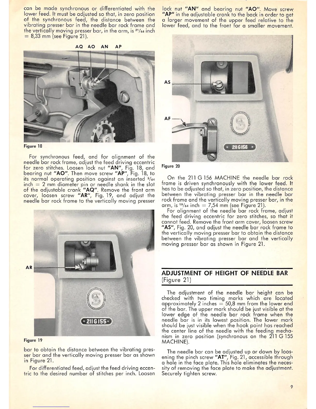
For synchronous feed, and for alignment of the
needle bar rock frame, adjust the feed driving eccentric
for zero stitches. Loosen
lock
nut "AN", Fig. 18, and
bearing nut "AO". Then move screw "AP", Fig. 18, to
its normal operating position against an inserted
V64
inch = 2 mm diameter pin or needle shank in the slot
of the
adjustable
crank
"AQ".
Remove the front arm
cover, loosen screw "AR", Fig. 19,
and
adjust the
needle
bar
rock frame to the vertically moving presser
Figure 19
bar
to obtain the distance between the vibrating pres
ser
bar
and
the vertically moving presser
bar
as shown
in Figure 21.
For differentiated feed, adjust the feed driving eccen
tric to the desired number of stitches per inch. Loosen
lock nut "AN" and bearing nut "AO". Move
screvy
"AP" in the adjustable crank to the back in order to get
a larger movement of the upper feed relative to the
lower
feed,
and
to
the
front for a
smaller
movement.
Figure 20
On
the
211
G156
MACHINE
the
needle
bar
rock
frame
is
driven
synchronously
with
the
lower
feed.
It
has to be adjusted so that, in zero position, the distance
between the vibrating presser
bar
in the needle
bar
rock
frame
and
the vertically moving presser
bar,
in the
arm, is
^V64
Inch = 7,54 mm (see Figure 21).
For alignment of the needle
bar
rock frame, adjust
the feed driving eccentric for zero stitches, so that it
cannot
feed.
Remove
the
front
arm
cover,
loosen
screw
"AS", Fig. 20,
and
adjust the needle
bar
rock frame to
the vertically moving presser
bar
to obtain the distance
between the vibrating presser
bar
and the vertically
moving presser
bar
as shown In Figure 21.
ADJUSTMENT
OF
HEIGHT
OF
NEEDLE
BAR
(Figure 21)
The adjustment of the
needle
bar
height can be
checked with two timing marks which
are
located
approximately
2 inches = 50,8 mm from the lower end
of the bar. The upper mark should be just visible at the
lower
edge
of the needle
bar
rock frame when the
needle
bar
is in its lowest position. The lower mark
should be just visible when the hook point has reached
the center line of the needle with the feeding mecha
nism in zero position (synchronous on the
211
G155
MACHINE).
The needle
bar
can be adjusted up or down by loos
ening the pinch screw "AT", Fig. 21, accessible through
a hole in the face plate. This hole eliminates the neces
sity of removing the face plate to make the adjustment.
Securely tighten screw.