INSTALLATION
OF
THE
MACHINE
(Figure 1)
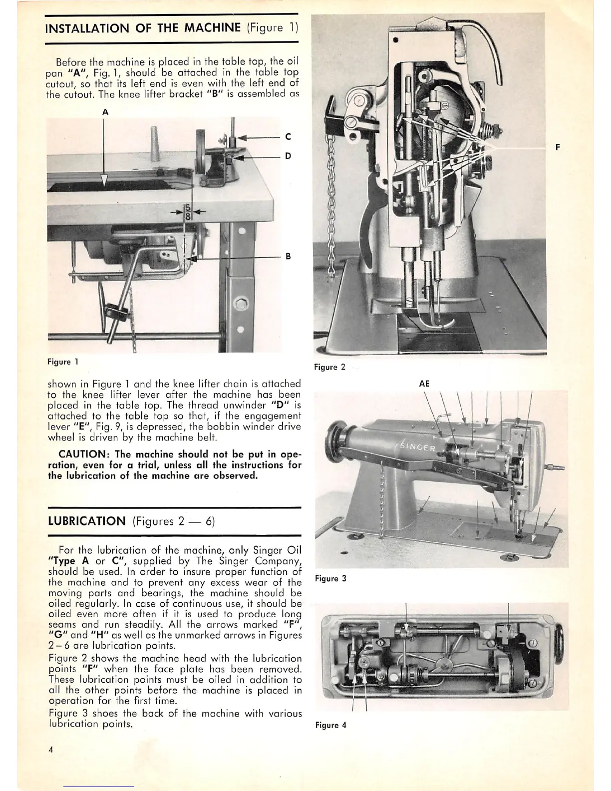
Before the machine is placed in the table top, the oil
pan "A",
Fig.
1,
should
be attached
in
the table top
cutout, so that its left end is even with the left end of
the
cutout.
The
knee
lifter
bracket
"B"
is
assembled
as
•mH
Figure 1
shown in Figure 1 and the knee lifter chain is attached
to
the
knee
lifter
lever
after
the
machine
has
been
placed in the table top. The thread unwinder "D" is
attached
to the
table
top
so that, if the
engagement
lever "E", Fig.9, is depressed, the bobbin winder drive
wheel is driven by the machine belt.
CAUTION: The machine should not
be
put
in
ope
ration,
even
for
a
trial,
unless
all
the
instructions
for
the
lubrication
of
the
machine
are
observed.
LUBRICATION (Figures 2 — 6)
For the lubrication of the machine, only Singer Oil
"Type A or C", supplied by The Singer Company,
should be used. In
order
to insure proper function of
the machine
and
to prevent any excess wear of the
moving
parts
and
bearings, the machine should be
oiled regularly. In
case
of continuous use, it should be
oiled even more often if it is used to
produce
long
seams
and
run steadily. All the
arrows
marked "F",
"G"
and
"H"
as well as the unmarked
arrows
in Figures
2-6
are
lubrication points.
Figure 2 shows the machine
head
with the lubrication
points
"F"
when the face
plate
has
been
removed.
These lubrication points must be oiled in addition to
all the other points before the machine is placed in
operation
for
the
first time.
Figure 3 shoes the back of the machine with various
lubrication points.
1
Figure 2
Figure 3
Figure 4