SETTING
THE
CLEARANCE
BETWEEN
NEEDLE
AND HOOK
POINT
(Continued)
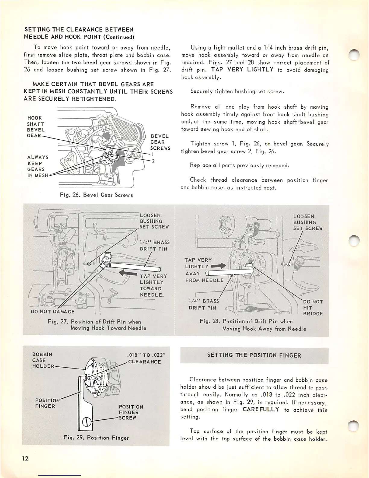
To move hook point toward or away
from
needle,
first remove
slide
plate, throat plate and bobbin
case.
Then, loosen the two bevel gear screws shown in Fig.
26 and loosen bushing set screw shown in Fig. 27.
MAKE
CERTAIN
THAT
BEVEL
GEARS
ARE
KEPT
IN MESH
CONSTANTLY
UNTIL
THEIR
SCREWS
ARE
SECURELY
RETIGHTENED.
HOOK
SHAFT
BEVEL
GEAR
BEVEL
GEAR
SCREWS
ALWAYS
KEEP
^ ^
GEARS
IN
MESH
Fig.
26. Bevel Geor
Screws
LOOSEN
BUSHING
SET
SCREW
1/4"
BRASS
DRIFT
PIN
TAP
VERY
LIGHTLY
TOWARD
NEEDLE.
DO
NOT
DAMAGE
12
Fig.
27.
Position
of Drift
Pin
when
Moving Hook
Toward
Needle
BOBBIN
CASE
HOLDER
POSITION
FINGER
1
.018"
TO
.022"
CLEARANCE
POSITION
FINGER
SCREW
Fig. 29.
Position
Finger
Using a light mallet and a 1/4 inch brass drift pin,
move
hook assembly toward or away
from
needle as
required. Figs. 27 and 28 show correct placement of
drift pin. TAP VERY LIGHTLY to avoid damaging
hook
assembly.
Securely tighten bushing
set
screw.
Remove all end play
from
hook shaft by moving
hook assembly
firmly
against front hook shaft bushing
and, at the some time,
moving
hook shaft'bevel gear
toward sewing hook end of shaft.
Tighten screw 1, Fig. 26, on bevel gear. Securely
tighten bevel
gear
screw 2, Fig. 26.
Replace all parts previously removed.
Check thread clearance between position finger
and
bobbin
case,
as
instructed
next.
TAP
VERY
LIGHTLY
AWAY
QZ
FROM
NEEDLE
1/4"
BRASS
DRIFT
PIN
LOOSEN
BUSHING
SET
SCREW
DO
NOT
HIT
BRIDGE
Fig.
28.
Position
of Drift
Pin
when
Moving Hook Away
from
Needle
SETTING
THE
POSITION
FINGER
Clearance
between position finger and bobbin
case
holder should be just sufficient to allow thread to pass
through easily. Normally an .018 to .022 inch clear
ance, as shown in Fig. 29, is required. If necessary,
bend position finger CAREFULLY to achieve this
setting.
Top surface of the position finger must be kept
level with
the
top
surface
of the bobbin
case
holder.