INSTALLATION
GASKET
PLUNGER
HIGH
MARK
OIL
RESERVOIR
LOW
MARK
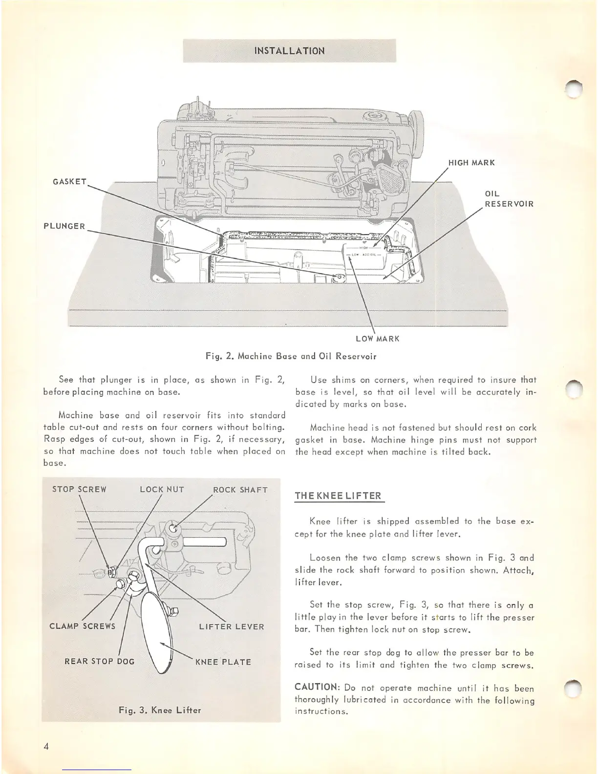
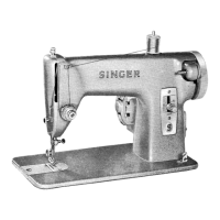
Fig.
2. Machine
Base
and
Oil
Reservoir
See that plunger is in place, as shown in Fig. 2, Use shims on corners, when required to insure that
before placing machine on
base,
base
is level, so
that
oil level will be
accurately
in
dicated
by marks on
bose.
Machine
base
and
oil
reservoir
fits
into
standard
table
cut-out and
rests
on four corners without bolting. Machine head is not
fastened
but should
rest
on cork
Rasp edges of cut-out, shown in Fig. 2, if necessary, gasket in base. Machine hinge pins must not support
so that machine does not touch table when placed on the head except when machine is tilted back,
base.
STOP
SCREW
LOCK
NUT
ROCK
SHAFT
CLAMP
SCREWS
LIFTER
LEVER
REAR
STOP
DOG
KNEE
PLATE
Fig.
3,
Knee
Lifter
THEKNEE
LIFTER
Knee lifter is shipped
assembled
to
the
base
ex
cept
for
the
knee
plate
and
lifter
lever.
Loosen
the two clamp
screws
shown in
Fig.
3
and
slide
the rock shaft forward to position shown. Attach,
lifter
lever.
Set the stop screw, Fig. 3, so that there is only a
little
play in
the
lever before it
starts
to lift
the
presser
bar. Then tighten lock nut on stop screw.
Set
the
rear
stop
dog to allow
the
presser
bar
to be
raised to
its
limit and tighten the two clamp screws.
CAUTION: Do not
operate
machine until it
has
been
thoroughly
lubricated in accordance
with
the
following
instructions.