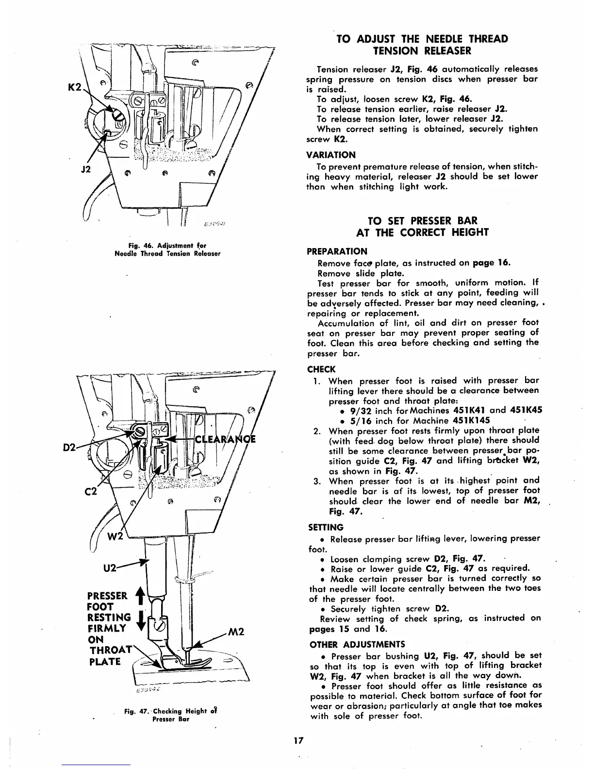
Fig. 46.
Adjustment
for
Needle
Thread
Tension
Releaser
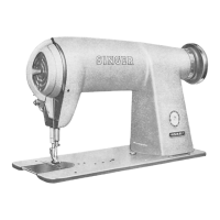
PRESSER
4
FOOT
•
RESTING
1
FIRMLY
T
ON
THROAT
PLATE
Fig.
47.'
Checking
Height
o?
Presser
Bar
TO
ADJUST
THE
NEEDLE
THREAD
TENSION
RELEASER
Tension
releaser
J2,
Fig.
46
automatically
releases
spring pressure on tension discs when presser
bar
is
raised.
To
adjust,
loosen
screw
K2, Fig.
46.
To
release
tension
earlier,
raise
releaser
J2.
To
release
tension
later,
lower
releaser
J2.
When correct setting is
obtained,
securely
tighten
screw
K2.
VARIATION
To
prevent
premature
release
of tension,
when
stitch
ing
heavy
material, releaser
J2
should be set lower
than
when
stitching
light
work.
TO
SET
PRESSER
BAR
AT
THE
CORRECT
HEIGHT
PREPARATION
Remove foctf plate, as instructed on
page
16.
Remove
slide
plate.
Test presser bar for smooth, uniform motion. If
presser bar tends to stick
at
any point, feeding will
be adversely affected. Presser
bar
may need cleaning, .
repairing
or
replacement.
Accumulation of lint, oil
and
dirt
on
presser
foot
seat on presser bar may prevent proper seating of
foot.
Clean
this
area
before
checking
and
setting
the
presser
bar.
CHECK
1. When presser foot is raised with presser bar
lifting lever there should be a clearance between
presser foot
and
throat
plate:
•
9/32
inch for Machines 451K4I
and
451K45
•
5/16
inch
for
Machine
451K145
2. When presser foot rests firmly upon throat plate
(with feed, dog below throat plate) there should
still be some clearance between presser^bar po
sition guide C2, Fig. 47
and
lifting bracket W2,
as
shown
in Fig.
47.
3. When presser foot is at its highest point and
needle
bar
is of its lowest, top of presser foot
should
clear
the
lower
end
of
needle
bar
M2,
Fig.
47.
SETTING
• Release presser
bar
lifting lever, lowering presser
foot.
• Loosen clamping screw D2, Fig. 47.
• Raise or lower
guide
C2, Fig. 47 as required.
• Make certain presser
bar
is turned correctly so
that
needle
will locate centrally
between
the
two toes
of the
presser
foot.
•
Securely
tighten
screw
D2.
Review setting of check spring, as instructed on
pages
15
and
16.
OTHER
ADJUSTMENTS
• Presser
bar
bushing U2, Fig. 47, should be set
so that its top is even with top of lifting bracket
W2, Fig. 47 when bracket is all the way down.
•
Presser
foot
should
offer
as
little
resistance
as
possible to material.
Check
bottom surface of foot for
wear or abrasion; particularly at angle that toe makes
with sole of
presser
foot.
17