SEHING
UP
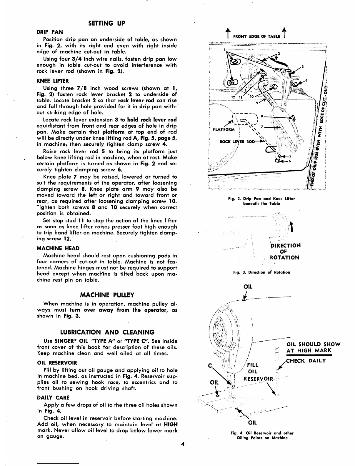
DRIP
PAN
Position
drip
pan
on
underside
of
table,
as
shown
in Fig. 2,
with
its
right
end
even
with
right
inside
edge
of
machine
cut-out
in
table.
Using four
3/4
inch
wire
nails,
fasten
drip
pan
low
enough
in
table
cut-out
to
ovoid
interference
with
rock
lever
rod
(shown
in Fig. 2).
KNEE
LIFTER
Using
three
7/8
inch
wood
screws
(shown
at
1,
Fig. 2)
fasten
rock
lever
bracket
2 to
underside
of
table.
Locate
bracket
2
so
that
rock
lever
rod
can
rise
and
fall
through
hole
provided
for it in
drip
pan
with
out
striking
edge
of
hole.
Locate
rock
lever
extension
3
to
hold
rock
lever
rod
equidistant
from
front
and
rear
edges
of hole in
drip
pan.
Make
certain
that
platform
at
top
end
of
rod
will be directly
under
knee lifting rod A, Fig. 5,
page
5,
in
machine;
then
securely
tighten
clamp
screw
4.
Raise rock
lever
rod 5 to bring its
platform
just
below
knee
lifting
rod
in
machine,
when
at
rest.
Make
certain
platform
is
turned
as
shown
in Fig. 2
and
se
curely tighten
clamping
screw
6.
Knee
plate
7
may
be
raised,
lowered
or
turned
to
suit
the
requirements
of
the
operator,
after
loosening
clamping
screw 8. Knee
plate
arm
9
may
also
be
moved
toward
the
left
or
right
and
toward
front
or
rear,
as
required
after
loosening
clamping
screw
10.
Tighten both screws 8
and
10 securely
when
correct
position is
obtained.
Set
stop
stud 11 to stop
the
action of
the
knee
lifter
as soon
as
knee
lifter
raises
presser
foot
high
enough
to trip
hand
lifter on
machine.
Securely
tighten
clamp
ing
screw
12.
MACHINE
HEAD
Machine
head
should rest
upon
cushioning
pads
in
four
corners
of
cut-out
in
table.
Machine
is
not
fas
tened. Machine hinges must not be
required
to
support
head
except
when
machine is tilted back upon ma
chine
rest pin on
table.
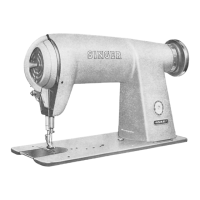
MACHINE
PULLEY
When
machine
is in
operation,
machine
pulley al
ways
must
turn
over
away
from
the
operator,
as
shown
in Fig.
3.
LUBRICATION
AND
CLEANING
Use
SINGER*
OIL
"TYPE
A"
or
'TYPE
C".
See
inside
front cover of this book
for
description of these oils.
Keep
machine
clean
and
well
oiled
at
all times.
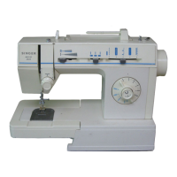
OIL
RESERVOIR
Fill
by lifting
out
oil
gauge
and
applying oil to hole
in
machine
bed,
as
instructed in Fig. 4. Reservoir
sup
plies oil to
sewing
hook race, to eccentrics
and
to
front
bushing
on
hook
driving
shaft.
DAILY
CARE
Apply
a
few
drops
of
oil to
the
three
oil
holes
shown
in Fig.
4.
Check oil level in reservoir
before
starting
machine.
Add oil,
when
necessary to
maintain
level
at
HIGH
mark. Never allow oil level to
drop
below lower
mark
on
gauge.
t
FRONT
EDGE
OF
TABLE
12 11
t
PLATFORM
\N
t
ROCK
LEVER
ROD—
is
;
<TV
v<-
Fig. 2. Drip Pan
and
Knee Lifter
beneath
the
Table
it
. ^
DIRECTION
OF
ROTATION
Fig. 3. Direction of Rotation
//)7
' -
'I
- t
OIL
SHOULD
SHOW
AT
HIGH
MARK
CHECK
DAILY
FILL
RESERVOIR
OIL
Fig. 4. Oil
Reservoir
and
other
Oiling Points on
Machine