Z3
P3
03
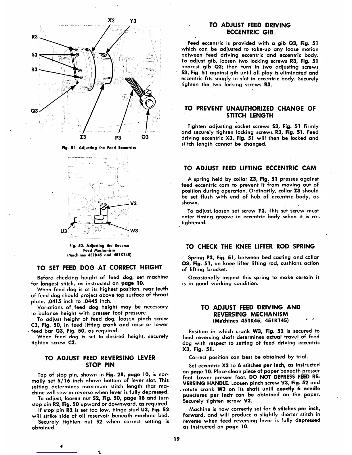
Fig. 51. Adjusting the Feed Eccentrics
U3
1
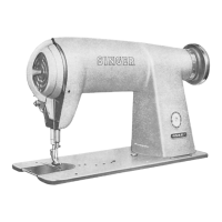
Fig. 52. Adjusting
the
Reverse
Feed
Mechanism
(Machines 451K45
and
451K145)
TO SET FEED
DOG
AT CORRECT HEIGHT
Before checking height of feed dog, set machine
for longest stitch,
as
instructed on
page
10.
When feed dog is
at
its highest position,
rear
teeth
of feed dog should project above top surface of throat
plate, .0415 inch to .0445 inch.
Variations
of
feed
dog
height
may
be
necessary
to
balance
height
with
presser
foot pressure.
To adjust height of feed dog, loosen pinch screw
C3, Fig. 50, in feed lifting crank
and
raise or lower
feed
bar
G3,
Fig.
50,
as
required.
When
feed
dog
is
set
to
desired
height, securely
tighten
screw
C3.
TO
ADJUST
FEED
REVERSING
LEVER
STOP
PIN
Top of stop pin, shown in Fig. 28,
page
10, is nor
mally set
5/16
inch above bottom of lever slot.
This
setting determines maximum stitch length
that
ma
chine will
sew
in reverse
when
lever is fully
depressed.
To adjust, loosen nut S2, Fig. 50,
page
18
and
turn
stop pin
R2,
Fig.50 upward or downward, as required.
If stop pin R2 is set too low, hinge stud U3, Fig. 52
will
strike
side
of
oil
reservoir
beneath
machine
bed.
Securely tighten
nut
S2
when
correct setting is
obtained.
TO
ADJUST
FEED
DRIVING
ECCENTRIC
GIB
Feed eccentric Is
provided
with
a
gib
Q3,
Fig. 51
which can be
adjusted
to.
take-up
any
loose motion
between feed driving eccentric
and
eccentric body.
To
adjust
gib,
loosen
two
locking screws R3, Fig. 51
nearest
gib
Q3;
then
turn in
two
adjusting
screws
S3, Fig. 51
against
gib
until all
ploy
is
eliminated
and
eccentric fits snugly in slot in eccentric body. Securely
tighten
the
two
locking
screws
R3.
TO
PREVENT
UNAUTHORIZED
CHANGE
OF
STITCH
LENGTH
Tighten
adjusting
socket
screws
S3, Fig. 51 firmly
and
securely
tighten
locking
screws
R3, Fig.
51.
Feed
driving
eccentric
X3, Fig. 51 will
then
be
locked
and
stitch
length
cannot
be
changed.
TO
ADJUST
FEED
LIFTING
ECCENTRIC
CAM
A
spring
held by collar Z3, Fig. 51
presses
against
feed
eccentric
cam
to
prevent
it
from
moving
out
of
position
during
operation.
Ordinarily,
collar Z3 should
be
set
flush with
end
of
hub
of eccentric body,
as
shown.
To
adjust,
loosen
set
screw
Y3. This
set
screw
must
enter
timing
groove
in
eccentric
body
when
it is
re-<
tightened.
TO
CHECK
THE
KNEE
LIFTER
ROD
SPRING
Spring P3, Fig. 51, between bed casting
and
collar
03,
Fig.
51,
on
knee
lifter lifting rod, cushions action
of
lifting
bracket.
Occasionally inspect this spring to moke certain it
is in
good
working
condition.
TO
ADJUST
FEED
DRIVING
AND
REVERSING
MECHANISM
(Machines
451K45,
451K145)
' '
Position in
which
crank
W3,
Fig.
52
is
secured
to
feed reversing
shaft
determines actual travel of
feed
dog with respect to setting of
feed
driving eccentric
X3,
Fig.
51.
Correct position can best be obtained by trial.
Set eccentric X3 to 6 stitches per inch, as instructed
on page 10.
Place
clean pieceof paper beneath presser
foot.
Lower
presser foot.
DO
NOT
DEPRESS
FEED
RE
VERSING
HANDLE.
Loosen
pinch screw V3, Fig. 52 and
rotate crank W3 on its
shaft
until exactly 6 needle
punctures per inch' can be obtained on the paper.
Securely
tighten
screw
V3.
Machine is now correctly set for 6 stitches
per
inch,
forward, and will produce a slightly shorter stitch in
reverse
when
feed
reversing lever is fully
depressed
as
instructed on
page
10.
19