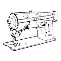
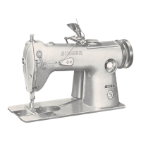
Figure 28
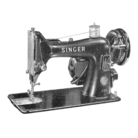
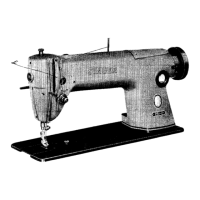
Figure 29
TO
SET
THE
NEEDLE
BAR
YOKE
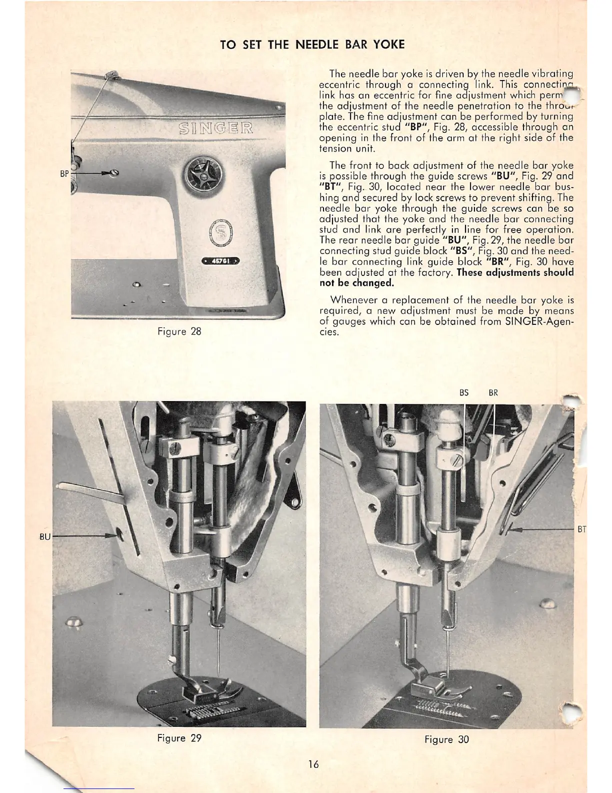
The needle
bar
yoke isdriven by the needle vibrating
eccentric through a connecting link. This connectirifl
link has an eccentric for fine adiustment which perm
the adjustment of the needle penetration to the
throo<-
plate. The fine adjustment can be performed by turning
the eccentric stud "BP", Fig. 28, accessible through an
opening in the front of the arm at the right side of the
tension
unit.
The front to back adjustment of the needle
bar
yoke
is possible through the guide screws "BU",
Fig.
29 and
"BT", Fig. 30,
located
near
the lower
needle
bar
bus
hing
ana
secured by lock screws to prevent shifting. The
needle
bar
yoke through the guide screws can
be
so
adjusted
that
the yoke
and
the needle
bar
connecting
stud
and
link
are
perfectly In line for free operation.
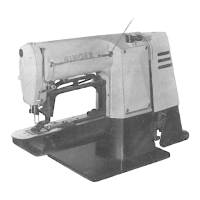
The
rear
needle
bar
guide
"BU", Fig.29, the
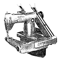
needle
bar
connecting stud
guide
block "BS", Fig. 30
and
the need
le
bar
connecting link guide block "BR", Fig. 30 have
been
adjusted
at the
factory.
These
adjustments
should
not be changed.
Whenever a replacement of the needle
bar
yoke is
required, a new adjustment must be made by means
of gauges
which
can be obtained from SINGER-Agen-
cies.
I
Figure 30
16
 Loading...