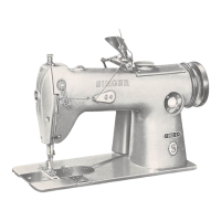
UPPER
THREADING
As soon
OS
the
operator
has become accustomed to
threading the machine, the thread can be passed with
a single continuous motion from the thread guide to the
needle eye.
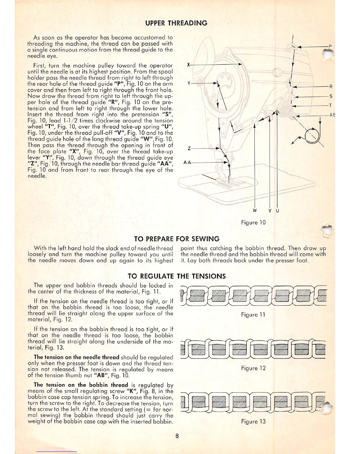
First,
turn
the
machine
pulley
toward
the
operator
until the needle Isat its hignest position. From the spool
holder pass the needle thread from right to left through
the rear hole of the thread guide "P", Fig.10 on the arm
cover
and
then from left to right through the front hole.
Now
draw
the
thread
from right to left through the up
per hole of the thread guide "R", Fig. 10 on the pre
tension
and
from left to right through the lower hole.
Insert the thread from right into the pretension "S",
Fig. 10, lead
1-1/2
times clockwise
around
the tension
wheel "T", Fig. 10, over the
thread
take-up spring "U",
Fig. 10,
under
the
thread
pull-off "V", Fig. 10
and
to the
thread guide hole of the long thread guide "W",
Fig.
10.
Then pass the thread through the opening in front of
the face plate "X", Fig. 10, over the thread take-up
lever "Y", Fig. 10, down through the thread guide eye
"Z", Fig. 10, through the needle
bar
thread guide "AA",
Fig. 10
and
from front to rear through the eye of the
needle.
Figure 10
TO
PREPARE
FOR
SEWING
With
the
left
hand
hold
the
slock
end
of
needle
thread
loosely and turn the machine pulley toward you
until
the needle moves down and up again to its highest
point
thus
catching
the
bobbin
thread.
Then
draw
up
the
needle
thread
and
the
bobbin
thread
will
come
with
it. Lay both threads back under the presser foot.
TO
REGULATE
THE
TENSIONS
The upper
and
bobbin threads should be locked in
the center of the thickness of the material. Fig. 11.
If the tension on the needle thread is too tight, or if
that
on the bobbin
thread
is
too
loose, the needle
thread
will
lie straight along the upper surface of the
material, Fig. 12.
If the tension on the bobbin thread is too tight, or if
that
on the needle
thread
is
too
loose, the bobbin
thread
will
lie straight along the underside of the ma
terial, Fig. 13.
Thetension on the needle thread should be regulated
only when the presser foot is down
and
the thread ten
sion not released. The tension is regulated by means
of the tension thumb nut "AB", Fig.10.
The tension on the bobbin thread
is
regulated by
means of the small regulating screw "K", Fig. 8, in the
bobbin case cap tension spring. To increase the tension,
turn the screw to the right. To decrease the tension, turn
the screw to the left. At the standard setting
(=
for nor
mal sewing) the bobbin thread should just carry the
weight of the bobbin case
cap
with the inserted bobbin.
Figure 11
Figure 12
Figure 13