© Oct. 2022 2-2 GTZZ18J Operation Manual
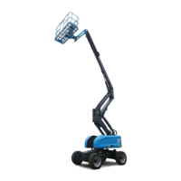
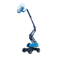
MACHINE COMPONENTS
Table 2-1
1. Jib boom 15. Reducer 29. Engine
2. Jib boom cylinder 16. Warning lamp 30. Steering cylinder
3. Upper leveling cylinder 17. Gear pump 31. Steering linkage
4. Main boom 18. Ground controller 32. Slewing mechanism
5. Telescopic boom 19. Front wheel 33. Cycloid motor
6. Cable track system 20. Storage battery 34. AC power receptacle (optional)
7. Turntable assembly 21. Hydraulic generator (optional) 35. Manual storage container (optional)
8. Main boom lift cylinder 22. Fuel tank 36. Foot switch
9. Connector 23. Hydraulic tank 37. Platform
10. Auxiliary leveling cylinder 24. Boom function manifold 38. Height limit device (optional)
11. Articulated boom leveling cylinder 25. Travel motor 39. Platform controller
12. Counterweight 26. Chassis 40. Working light (optional)
13. Power unit 27. Rear wheel 41. Closed-circuit variable pump
14. Turntable cover (RH) 28. Turntable cover (LH) 42. Articulated boom
Machine positions
Stowed position:
Articulated boom descends in place, and main boom
descends and retracts in place.
Non-operating position:
Articulated boom descends in place, and main boom
descends and retracts in place.
Operating/raised position:
Articulated boom not descends in place, or main
boom not descends or retracts in place.