1 GENERAL INFORMATION AND DESIGN
ATTENTION! Changing the batteries causes loss of time, if Tango_Plus is not connected
to external power supply at the same time.
1.3 Design
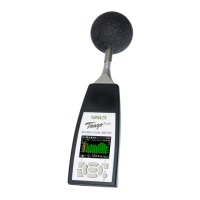
Figure 1.3: Design of the device
Tango_Plus contains the following parts:
detachable microphone with preampli-
fier, casing, display, keypad and battery
compartment. Opening the device is
only necessary for replacing the batter-
ies (figure 1.2.1).
At the bottom of the device the USB
socket is located for connecting the
device to a PC (type mini five-pole). Next
to it there is a socket for a 3.5 mm stereo
jack. This monitoring output is used
to connect a headset for example, it is
not approved for legally binding mea-
surements. Furthermore Tango_Plus
provides a socket to connect a printer
directly.
A detailed description of the display and
keypad is given in the paragraphs 1.3.2
and 1.3.1. Pay also attention to the notes
given in paragraph 1.1.
ATTENTION! For legally binding measurements Tango_Plus has to be powered only by
battery. The monitoring output is not approved for this.
1.3.1 Keypad
If the device is not controlled via PC, you may also use the keypad for setup. In the middle it contains arrow
keys with an OK-button in the center. The top corners contain function keys, whose functions are indicated
by symbols on the display. The key below on the left is used to start and pause measurements, while the
one on the right switches on the device and toggles the brightness level.
1.3.2 Display
The display shows the measured values and is used for setting up the device. It is refreshed every 500 ms.
The status bar on the top of the display shows symbols for: Battery, Memory, Play/Pause, Storage, Calibra-
Manual Tango_Plus 8 of 30 SINUS Messtechnik GmbH