24
OPERATING INSTRUCTIONS….cont
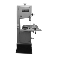
Upper guide:
The lateral support bearings should be set so that they are approximately 0.5 mm
away from the blade.
• Loosen (no need to remove) the bearing support screws (A).
• Slide the bearing assembly left / right until it is in the correct position.
• Re-tighten the bearing support screws.
A
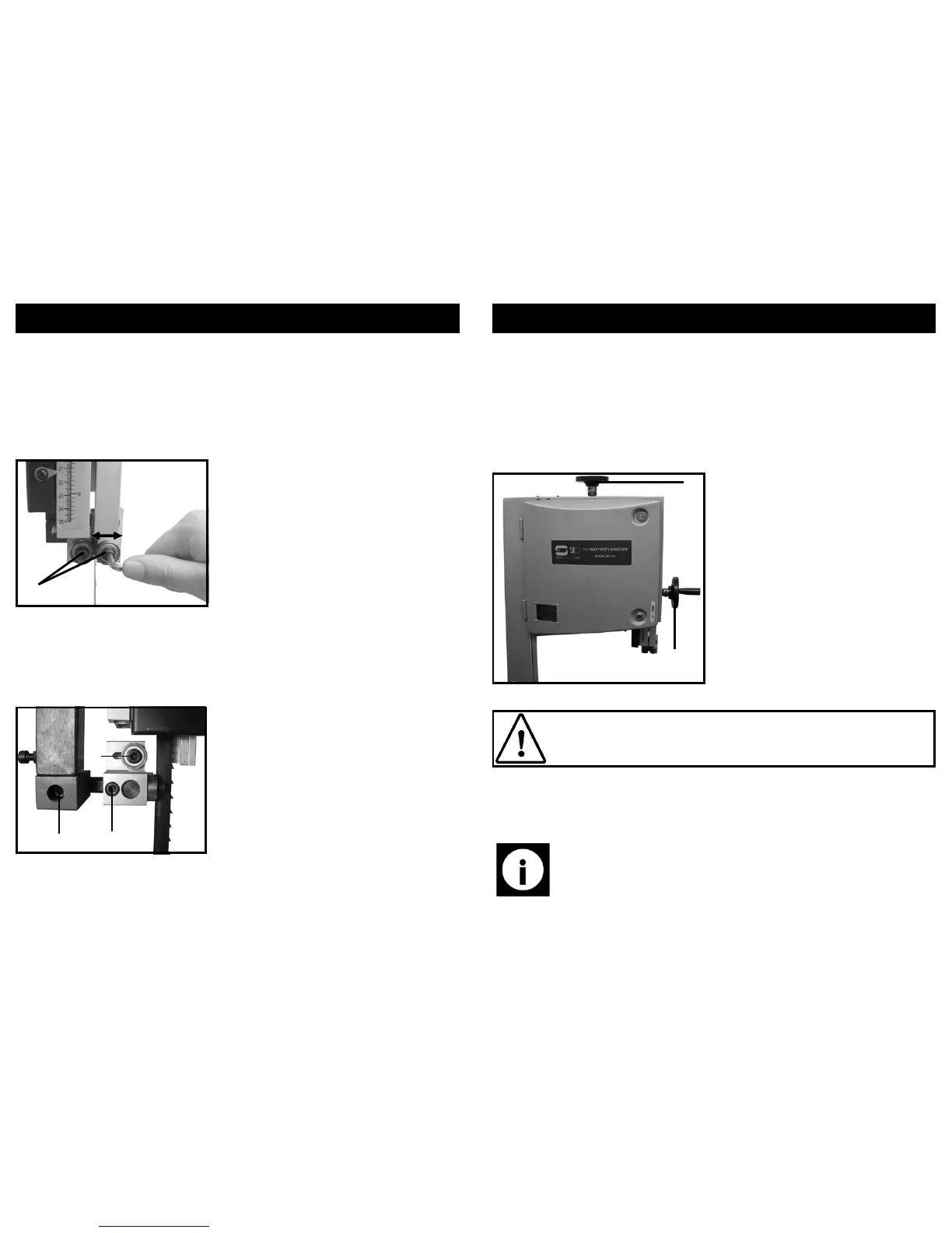
The rear thrust bearings should be set so that they are approximately 3 mm behind the
blade. They will only come into contact with the blade as the work-piece is being cut.
Due to the many different sizes of band-saw blades available, the rear support bearing
needs to have extra movement compared to the lateral support bearings. This is
achieved by having 3 different points of movement as opposed to 1 on the lateral sup-
port bearings.
A B
C
• Loosen the required allen bolt/s.
• Move the bearing, bearing assembly and/or the pole until the bearing is set in
the correct position.
• Re-tighten all of the allen bolts to secure the bearing in place.
Allen bolt A - This allows the bearing assembly
support pole to be moved and should be utilised
when large movement is required.
Allen bolt B - This allows the bearing support
assembly to be moved on the pole.
Allen bolt C - This allows the bearing to move
along the channel on the bearing support as-
sembly and should be utilised when only a small
amount of movement is required.
17
ASSEMBLY INSTRUCTIONS….cont
This machine is supplied partly assembled, Prior to use, the following items need to be
fitted to the band saw:
• The bearing guide hand-wheel
• The blade tension hand-wheel
• The main table
• The rip-fence guide rail
Fitting the blade tension and bearing guide hand wheel’s (A and B):
• Fit the table onto the table trunnion (C) ensuring that the 4 holes on the trun-
niun line up with the threaded holes on the bottom of the main table.
• Fit 4 x M8 x 16 mm securing bolts (D) and hand tighten to secure.
A
B
• Fit the blade tension hand wheel (A)
onto the thread rod, gravity will hold
it in place.
• Fit the bearing guide hand wheel (B)
onto the shaft of the worm gear.
• Secure with the supplied grub screw.
Note: The bolts only need to be hand tightened at this point as some ad-
justment may be necessary to set the table correctly.
Fitting the table:
Caution: Due to the weight of the main saw bed and other factors, this
operation would ideally be carried out by at least 2 persons to reduce the
risk of personal injury and / or damage to the machine.