18
ASSEMBLY INSTRUCTIONS….cont
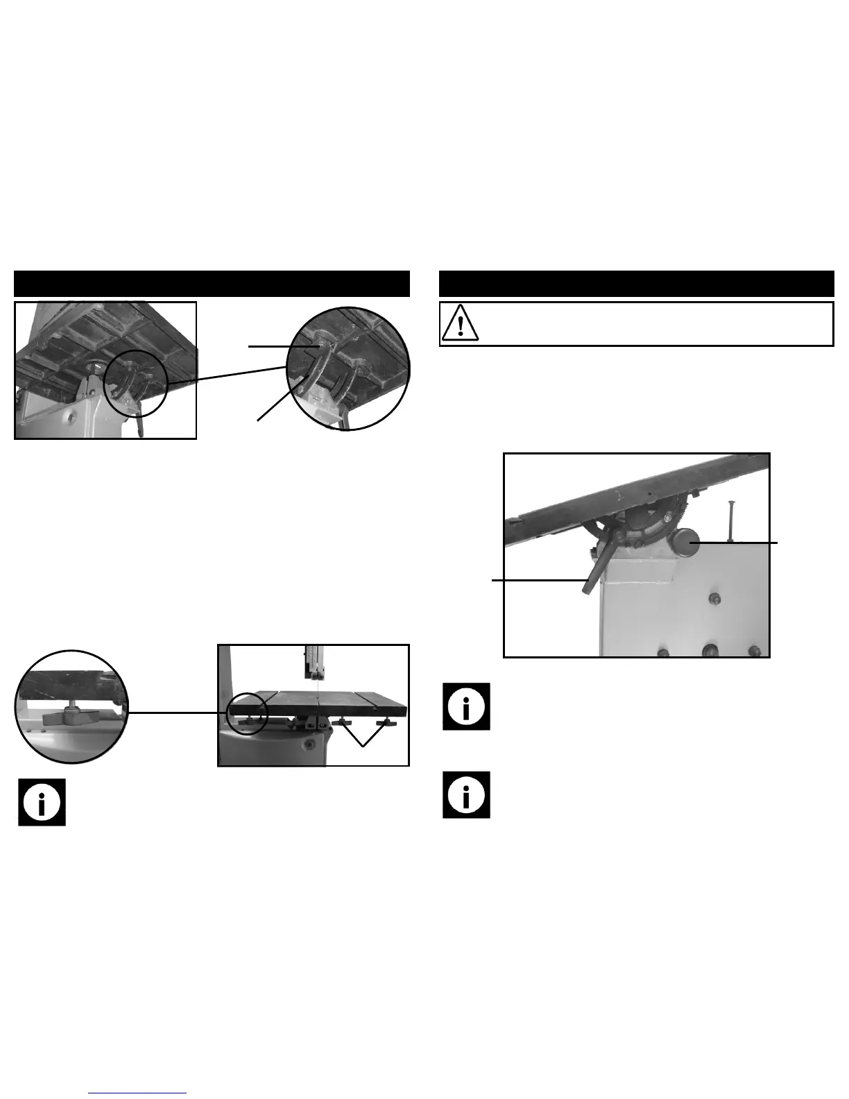
C
D
Note: The winged screws (E) only need to be fitted with a few turns so
there is an adequate gap to fit the rip-fence guide (F).
Setting the table in the correct position:
This instruction assumes that the blade is already fitted, if not, go to the section
headed “ Replacing the band saw blade”.
• The blade should sit in the centre of the gap on the table insert, if it does not
tap the edge of the table (either left or right depending on which way the table
needs to go) with a mallet (a scrap piece of wood and a hammer will suffice if a
mallet is not available) until the blade is in the correct position.
• Proceed to fully tighten the securing bolts (D).
Fitting the rip fence guide:
• To fit the Rip Fence, firstly fit the 4 x winged screws and washers (E) supplied
into the 4 threaded holes on the bottom of the main table.
E
23
OPERATING INSTRUCTIONS….cont
Tilting the table to perform bevel cuts:
• loosen the table tilt locking lever (T).
• Turn the table tilt knob (P) to tilt the table to the desired angle.
• Re-tighten the tilt locking lever (T).
Note: Compound mitre cuts can be made by using the mitre gauge in
conjunction with the table tilting facility.
Table tilt
locking
lever (T)
Table tilt
knob (P)
Setting up the blade guides:
Caution: Always ensure that the saw is turned off and that the
mains lead is removed from the power supply before carrying out
any adjustments or maintenance.
Note: The blade guide minimises blade movement during the cutting op-
eration and ensures a safe accurate cut.