18
OPERATING INSTRUCTIONS….cont
The required tungsten diameter is determined by the thickness of the material to be
welded, for each tungsten size there are strict current limits which should be adhered
to. Too great a current causes excessive tungsten consumption and weld pool con-
tamination, whilst a too small a current causes arc instability.
The table below gives a guide as to which tungsten is most suitable according to the
material thickness. This table is only a guide, and values given are a indication only.
These welding current values are for thorium 2% (red) tungsten electrodes.
Welding
Thickness mm
Tungsten
Diameter mm
Welding Current
Steel
Welding Current
Stainless Steel
0.5 1.0 30-60 15-30
1.0 1.6 50-70 50-70
1.5 1.6 90-110 60-90
2.0 1.6 100-130 80-100
3.0 2.4 120-140 100-130
4.0 2.4 150-190 130-170
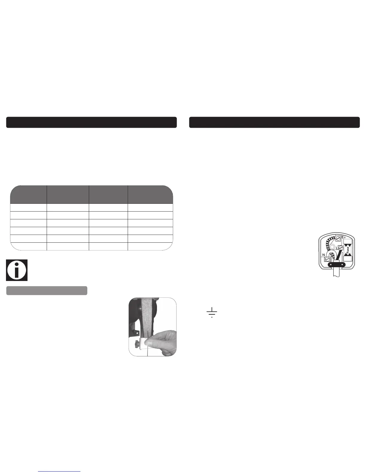
It is important to choose a tungsten with the correct diame-
ter for the current to be used. The tungsten will normally pro-
trude from the ceramic nozzle by 2 or 3mm, in order to
gain access to areas such as internal corners the tungsten
can be made to protrude by up to 8mm. The tungsten
should be sharpened facing the grinding wheel (see right
picture). The tip should be perfectly concentric in order to
avoid arc deviations. It is best to regularly inspect the tung-
sten to maintain peak condition.
Note: The above is a guide only; always try a short weld test at the setting
selected. It is normal to make minor adjustments to achieve the required
weld.
PREPARING THE TUNGSTEN
11
ELECTRICAL CONNECTION
Warning! It is the responsibility of the owner and the operator to read, understand and
comply with the following:
You must check all electrical products, before use, to ensure that they are safe.
You must inspect power cables, plugs, sockets and any other connectors for wear or
damage.
You must ensure that the risk of electric shock is minimised by the installation of appro-
priate safety devices; A residual current circuit Breaker (RCCB) should be incorporated
in the main distribution board. We also recommend that a residual current device
(RCD) is used. It is particularly important to use an RCD with portable products that are
plugged into a supply which is not protected by an RCCB. If in any doubt consult a
qualified electrician.
Connecting to the power supply 05703 & 05705:
These SIP Inverter welders (05703 & 05705) are fitted with a standard 230v ~ 13 amp
type plug. Before using the Inverter welder, inspect the mains lead and plug to ensure
that neither are damaged. If any damage is visible have the welder inspected / re-
paired by a suitably qualified person. If it is necessary to replace the plug a heavy
duty impact resistant plug would be preferable.
The wires for the plug are coloured in the following way:
Yellow / green Earth
Blue Neutral
Brown Live
As the colours of the wires may not correspond with the markings in your plug, pro-
ceed as follows: The wire which is coloured blue, must be connected to the terminal
marked with N or coloured black. The wire which is coloured brown, must be connect-
ed to the terminal, which is marked L or coloured red. The wire which is coloured yel-
low / green should be connected to the terminal which is coloured the same or
marked
Always secure the wires in the plug terminal carefully and tightly. Secure the cable in
the cord grip carefully.
 Loading...