4
When using your inverter welder, basic safety precautions should always be followed
to reduce the risk of personal injury and / or damage to the inverter welder.
Read all of these instructions before operating the inverter welder and save this user
manual for future reference.
The inverter welder should not be modified or used for any application other than that
for which it was designed.
This inverter welder was designed to supply electric current for ARC and TIG welding.
If you are unsure of its relative applications do not hesitate to contact us and we will
be more than happy to advise you.
Before each use of the inverter welder always check no parts are broken and that no
parts are missing.
Always operate the inverter welder safely and correctly.
KNOW YOUR INVERTER WELDER: Read and understand the owner's manual and labels
affixed to the inverter welder. Learn its applications and limitations, as well as the po-
tential hazards specific to it.
KEEP WORK AREA CLEAN AND WELL LIT: Cluttered work benches and dark areas invite
accidents. Floors must not be slippery due to oil, water or sawdust etc.
DO NOT USE THE INVERTER WELDER IN DANGEROUS ENVIRONMENTS: Do not use the
inverter welder in damp or wet locations, or expose it to rain. Provide adequate space
surrounding the work area. Do not use in environments with a potentially explosive at-
mosphere.
KEEP CHILDREN AND UNTRAINED PERSONNEL AWAY FROM THE WORK AREA: All visitors
SAFETY SYMBOLS USED THROUGHOUT THIS MANUAL
SAFETY INSTRUCTIONS
Important: Please read the following instructions carefully, failure to do
so could lead to serious personal injury and / or damage to the invert-
er welder.
Danger / Caution: Indicates risk of personal injury and/or the possibility of
damage.
Warning: Risk of electrical injury or damage!
Note: Supplementary information.
25
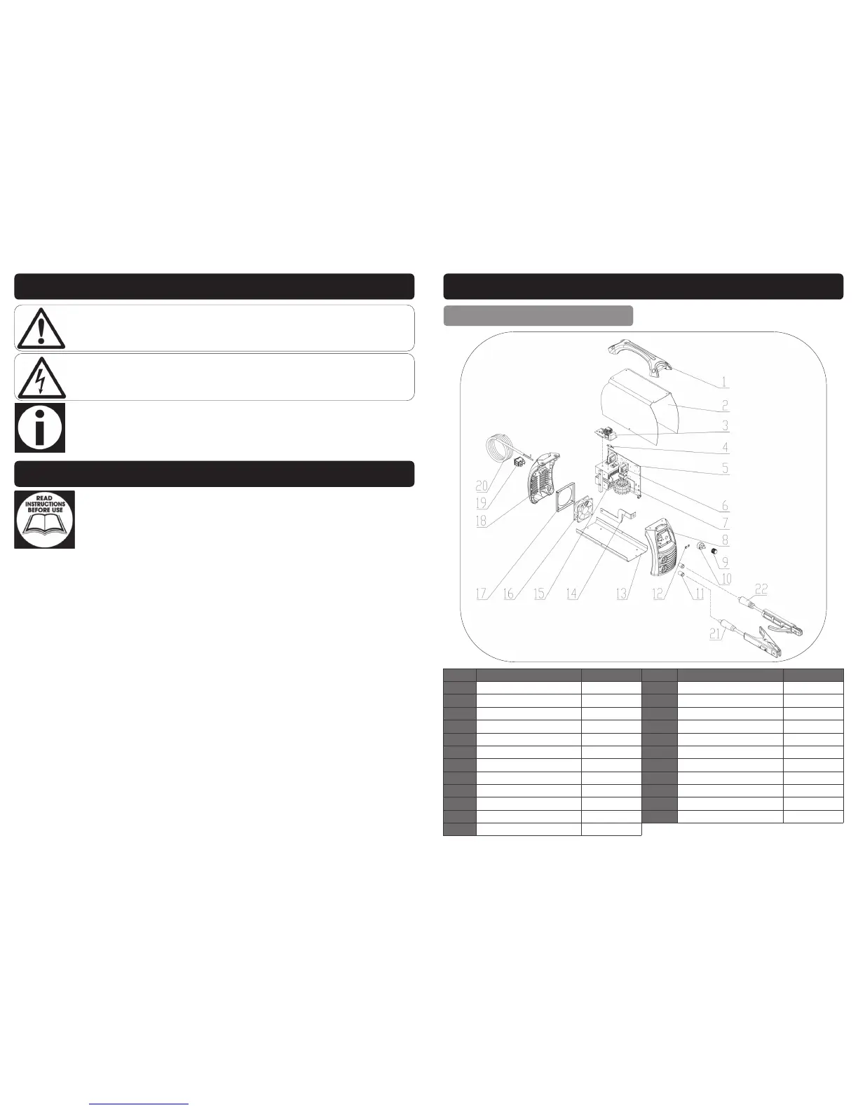
EXPLODED DRAWING / PARTS LIST
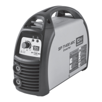
T1400 (05705)
Ref. No. Description Sip Part No. Ref. No. Description Sip Part No.
1. Handle WE07-00051 13. Chassis WE07-00063
2. Cover WE07-00072 14. Positive Output Busbar WE07-00076
3. EMC Board WE07-00073 15. Electrolytic Capacitor WE07-00065
4. NTC Resistance WE07-00054 16. Fan WE07-00077
5. Main Control PCB WE07-00074 17. Fan Fixing Plate WE07-00067
6. Power Transformer WE07-00056 18. Plastic Rear Cover WE07-00068
7. Main Transformer WE07-00075 19. Main On/Off Switch WE07-00069
8. Front Plastic Panel WE07-00058 20. Mains Lead WE07-00070
9. Potentiometer knob WE07-00059 21. Earth Lead c/w Clamp WE07-00037
10. Potentiometer WE07-00060 22.
Welding cable c/w Electrode Holder
WE07-00036
11. Dinse Socket WE07-00061 N/A Front Cover Sticker WE07-00078
12. LED Holder WE07-00062
 Loading...