26
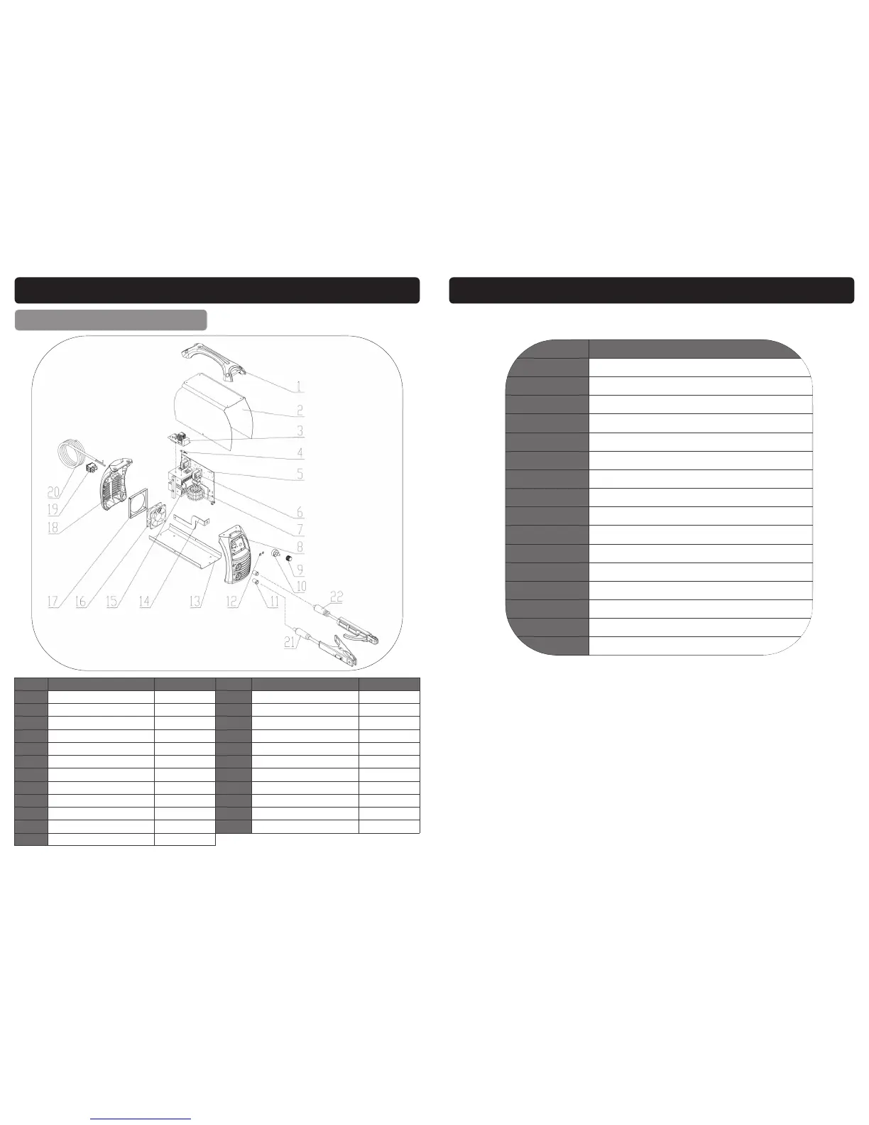
EXPLODED DRAWING / PARTS LIST
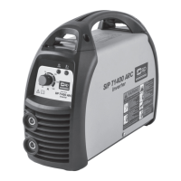
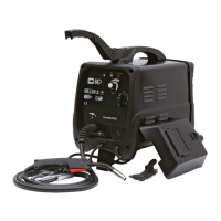
T1600 (05707)
Ref. No. Description Sip Part No. Ref. No. Description Sip Part No.
1. Handle WE07-00051 13. Chassis WE07-00063
2. Cover WE07-00079 14. Positive Output Busbar WE07-00076
3. EMC Board WE07-00080 15. Electrolytic Capacitor WE07-00081
4. NTC Resistance WE07-00054 16. Fan WE07-00077
5. Main Control PCB WE07-00081 17. Fan Fixing Plate WE07-00067
6. Power Transformer WE07-00056 18. Plastic Rear Cover WE07-00068
7. Main Transformer WE07-00075 19. Main On/Off Switch WE07-00069
8. Front Plastic Panel WE07-00058 20. Mains Lead WE07-00082
9. Potentiometer knob WE07-00059 21. Earth Lead c/w Clamp WE07-00037
10. Potentiometer WE07-00060 22.
Welding cable c/w Electrode Holder
WE07-00036
11. Dinse Socket WE07-00061 N/A Front Cover Label WE07-00083
12. LED Holder WE07-00062
3
CONTENTS
Page No. Description
4. Safety Symbols Used Throughout This Manual
4. Safety Instructions
11. Electrical Connection
13. Guarantee
13. Contents and Accessories
14. Technical Specification
15. Getting to Know Your Inverter Welder
16. Operating Instructions
20. Maintenance
21. Troubleshooting
22. Wiring Diagram - T800 (05703)
23. Wiring Diagram - T1400 (05705) / T1600 (05707)
24. Exploded Drawing / Parts List T800 (05703)
25. Exploded Drawing / Parts List T1400 (05705)
26. Exploded Drawing / Parts List T1600 (05707)
27. Declaration of Conformity