Sirona Dental Systems GmbH 1 Preparations
Installation Requirements C8
+
60 28 000 D3417
D3417.021.04.09.02
9
båÖäáëÜ
• Observe the national regulations for electrical installa-
tions (e.g. VDE 0100, VDE 0100, Part 710).
• Observe the national regulations for water supply in-
stallations (e.g. EN 1717, DIN 1988) and sewage instal-
lations (e.g. EN 12056-1).
• For the suction pipe, observe the instructions in the
Suction Machine Installation Instructions.
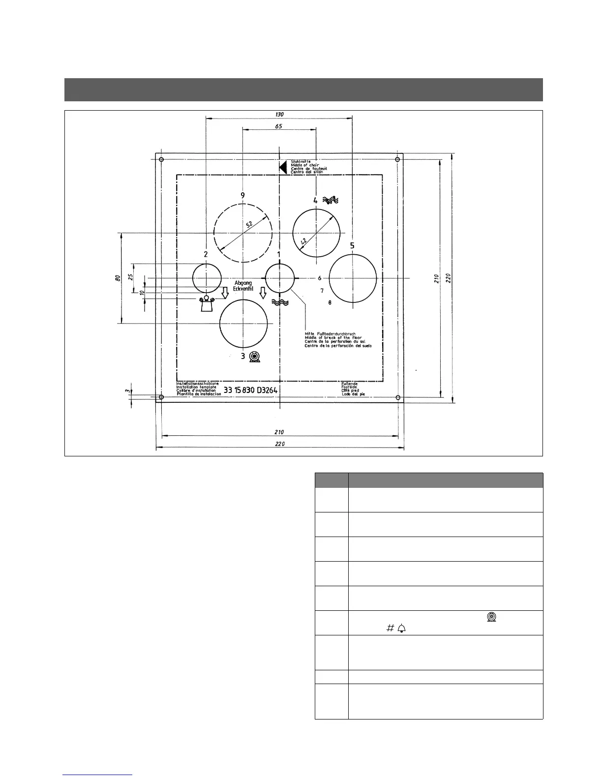
• For fastening the pipe ends in the installation field, we
recommend using an installation template. They can
be ordered from Sirona under REF 33 15 830.
If necessary, you can also prepare the template your-
self based on the above sketch (not true to scale!).
Supply lines in the termination panel
Table 1: Supply lines
Item Description
1 Water inlet pipe 10x1mm,
corner valve outlet 3/8"
2 Compressed air inlet pipe 10x1mm, corner
valve outlet 3/8"
3 Suction pipe DN40 HT-PP DIN 19560 (polypro-
pylene, inner diameter 36.5mm!)
4 Water drain DN40 HT-PP DIN 19560 (polypro-
pylene, inner diameter 36.5mm!)
5 Installation pipe, DN40 HT-PP DIN 19560
(polypropylene, 40mm!)
6 Suction machine control cable ( )and call
cables ( ) 3x1.5mm
2
7 Power cable 3x1.5mm
2
Fuse: 16A slow-blow
Recommended: Type B automatic circuit breaker
8 not applicable
9 Installation pipe (or corresponding flat duct) for
additional requirement e.g. practice network
connecting cable