ASSEMBLY STEPS
19
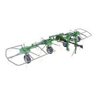
15. (MX 10 only)
Attach end sections 3 & 4 (LH - RH) to sections 1 & 2 (LH - RH) using screws 5 and nuts 6.
Insert bushings 7 in the correct
openings in end sections 3 & 4 (LH -
RH) and fasten in place with spring
pins 8.
In this step, you will use:
Item 5:
8 - screws M 16 x 45
(5/8" x 1" 3/4)
Item 6:
8 - nuts M 16
(5/8")
Item 8:
2 - spring pins D 8 x 70
(D 5/16" x 2" 3/4)
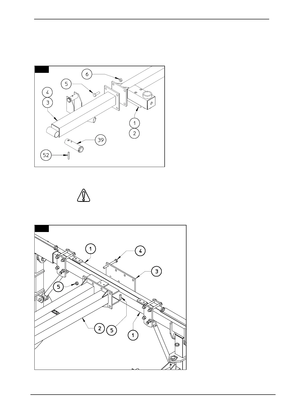
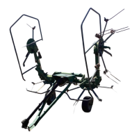
16. DANGER
This operation is to be carried out with the aid of supports and a jack or hoist of suitable
capacity. Weight of Part 2:
110 kg, 245 lbs.
NOTE: Assemble the
drawbar 2 in the middle of
the cross members 1 only
when the cross members 1
are pulled in together, so
the drawbar 2 and
counterplate 3 must be
assembled between ledges
6 (see also figure 46).
Attach drawbar 2 to cross
member assembly 1 using
counterplate 3, screws 4
and nuts 5.
in this step, you will use:
Item 4:
8 - screws M 16 x 165
(5/8" x 5" 3/8)
Item 5:
8 - nuts M 16
(5/8")
16
15