ASSEMBLY STEPS
22
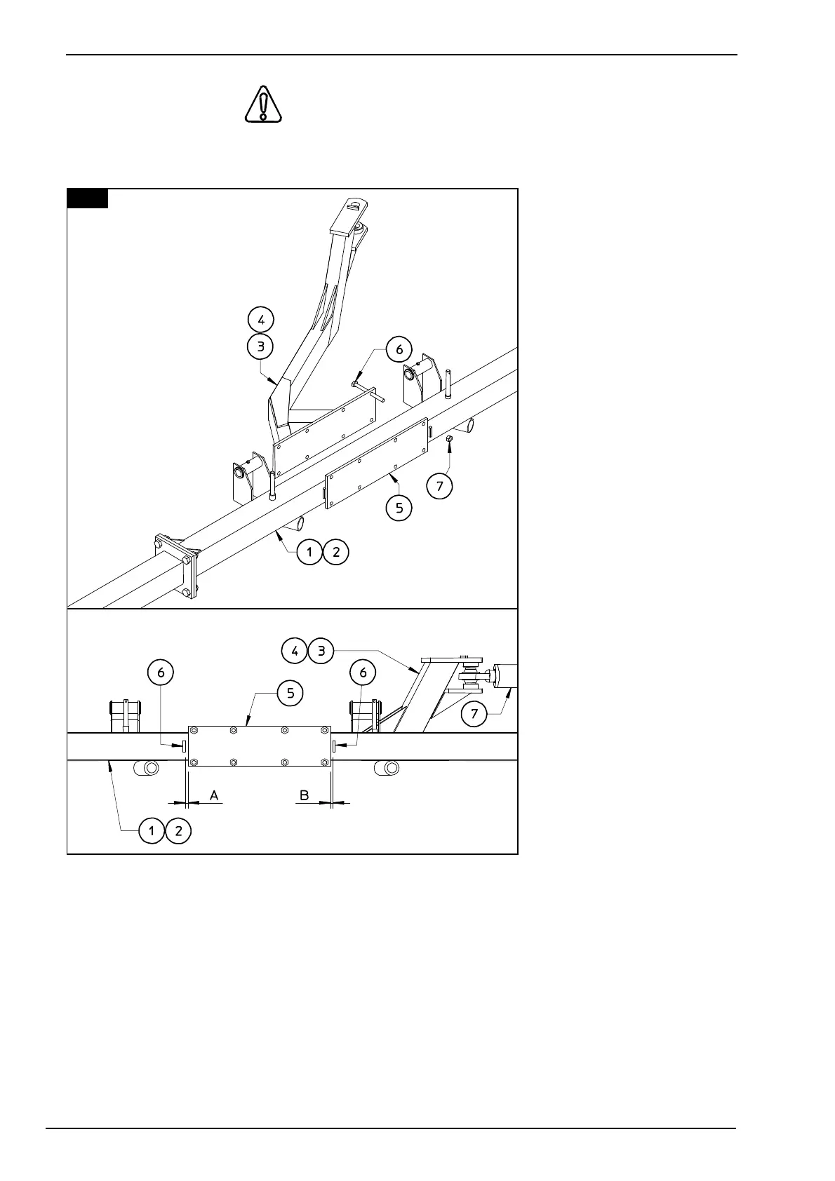
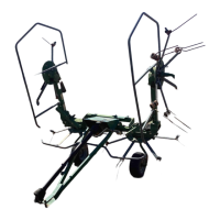
20. ATTENTION
Attach arms 3 & 4 (LH - RH) and counterplates 5 & 5a (LH - RH) to sections 1 & 2 (LH - RH),
fastening them with screws
6 and nuts 7. See diagram
for the correct positioning
of the parts.
NOTE: When the machine
is completely closed
(cylinder 7), regolate the
distances A & B with the
ledges 6 to make the wheel
section 1 & 2 (LH & RH) in
parallel.
In this step, you will use:
Item 6:
16 - screws M 12 x 140
(D 15/32" x 5" 1/2)
Item 7:
16 - nuts M 12
(15/32")
20