ASSEMBLY STEPS
28
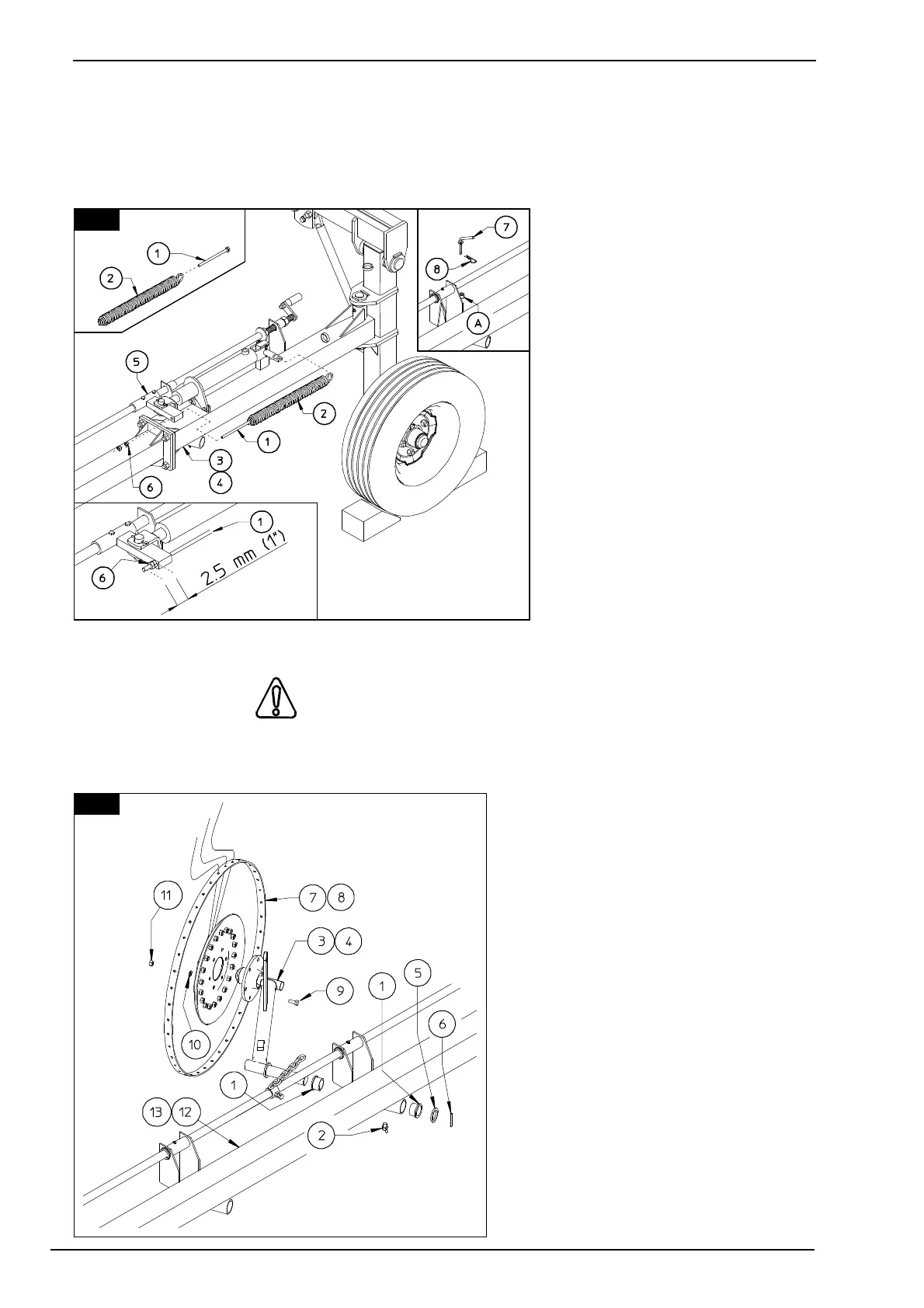
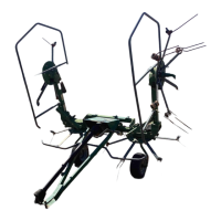
25.
First of all place stay bolts 1 inside springs 2. Attach spring 2 with stay bolt 1 to sections 3 & 4
(LH - RH) and attachments 5
as shown, fastening the spring-
bolt assembly in place with
nuts 6. Pasten stay bolts 1 with
nuts 3 so that they extend 25
mm (1") from attachment 5, as
shown.
Insert pins 7 in the correct
holes A, and fasten with clip 8.
In this step, you will use:
Item 6:
4 - nuts M10 (D 25/64")
Item 8:
2 - clips D 3 (1/8").
Item 9:
2 - pins D 10 x 48
(D 25/64" x 1" 7/8")
Item 7:
2 - pins D 10 x 63 (D 25/64" x
3" 30/64")
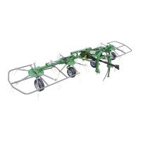
26. CAUTION
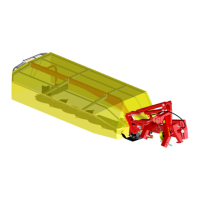
Attach bushings 1 and grease nipple 2 to rake wheel sections 12 & 13 (LH - RH) as shown.
Attach rake wheel brackets 3 & 4 (LH
- RH) to sections 12 & 13 (LH - RH)
and fasten with washers 5 and spring
pins 6. Mount rake wheels 7 & 8 (LH -
RH) to rake wheel arms 3 & 4 (LH -
RH) and fasten with screws 9, grower
washers 10 and nuts 11.
In this step, you will use:
Item 1:
20/16 - bushings D 35-42 x 26
(D 1" 3/8-1" 11/16 x 1")
Item 2:
10/8 - bent grease nipples M 6
(15/64")
Item 5:
10/8 - washers D 35-50 x 5
(D 1" 3/8-2" x 3/16")
25
26