CENTRAL WHEELS KIT
51
9.6
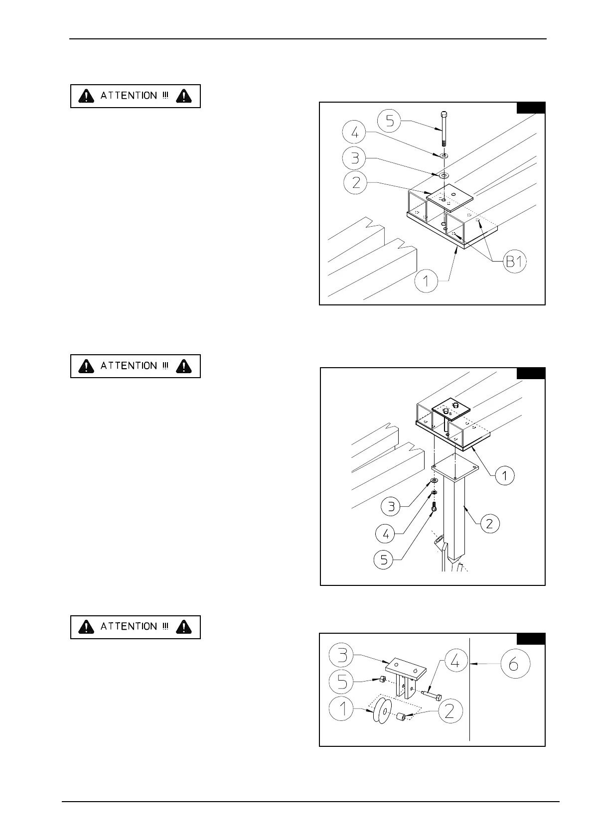
Place plate 1 against the lower part of the
drawbar and fasten it with counterplate 2,
washers 3-4
and screws 5. For positioning, see point 1.
Note : the B1 pair of holes should
must be positioned as shown in the
drawing.
In this step, you will use:
Item 3: 2 washers ø13 (1/2")
Item 4: 2 spring washers ø13
(1/2")
Item 4: 2 screws M12 x 130
(1/2" x 5 1/8")
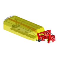
9.7
Attach support 2 to plate 1
using washers 3 - 4 and
screws 5.
In this step, you will use:
Item 3: 4 washers ø13 (ø1/2")
Item 4: 4 spring washers ø13
(ø1/2")
Item 5: 4 screws M12x25
(1/2" x 1")
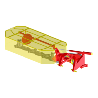
9.8
Mount pulley 1 and bush 2 into
bracket 3 using special screws 4
and nuts 5.
In this step, you will use:
Item 4: 1 special screw M12x70
(1/2" x 2 3/4")
Item 5: 1 nut M12 (1/2")