Section 05 ELECTRICAL
Sub-Section 07 (TESTING PROCEDURE)
05-07-5
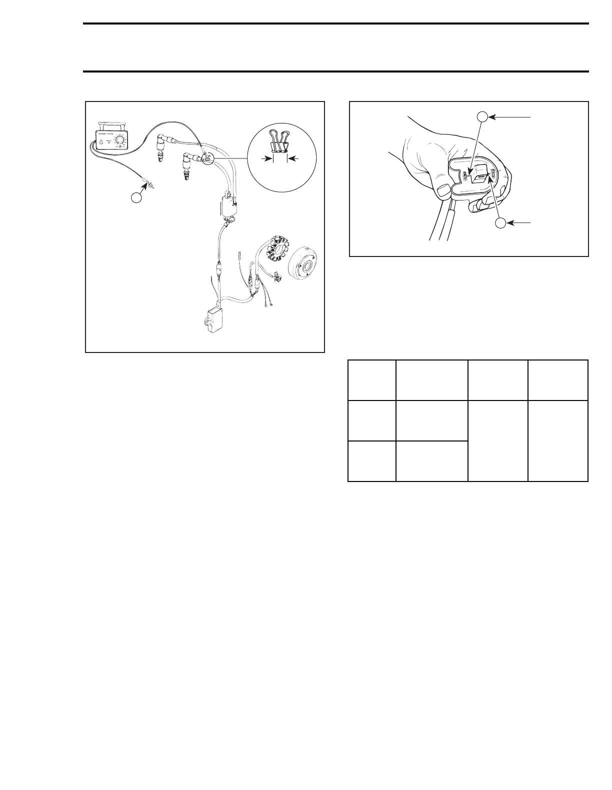
TYPICAL
1. Engine ground
2. MAG side
A. 20 mm (3/4 in)
3. Crank engine and observe indicator.
NOTE:
If engine starts, allow it to idle while
observing indicator. Then, shut engine off.
4. Push reset button and repeat step 3 twice.
Results:
a.
Indicator lamp lights:
Ignition system is OK.
b.
Indicator lamp does not light on one or
both cylinder:
Proceed to following tests.
IGNITION MODULE
1. Disconnect both connectors at ignition coil.
At assembly, secure with new locking ties.
2. Connect an ignition coil (known as being in
good condition) to the spark plug(s).
3. Connect CDI module to replacement ignition
coil paying attention to connect the WHITE/
BLUE wire to the positive (+) terminal and the
BLACK wire to the negative (–) terminal.
1. Black
2. White/Blue
4. Slip plastic protectors out of coil terminals.
5. Connect tester wires to coil terminals then set
switch and dial as follows:
NOTE:
If necessary use jumper wires from
coil terminals to tester wires.
A15E0SA
N
1
2
A
Tester
wires
Component
wires
Tester
switch
position
Tester
dial
position
N
WHITE/BLUE
wire (+)
of ignition coil
LOW 85
P
BLACK
wire (−)
of ignition coil
A00E1JA
+
_
1
2