Section 03 ENGINE
Sub-Section 03 (454, 494, 583 AND 670 ENGINE TYPES)
03-03-7
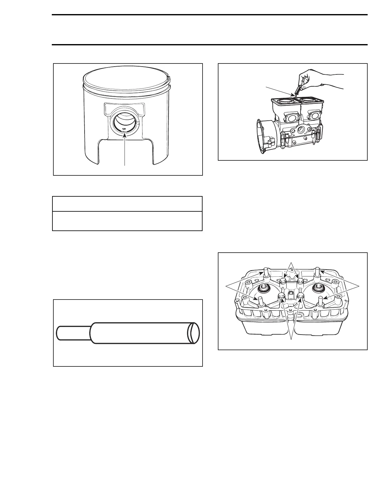
TYPICAL
1. Circlip break
22, Cylinder
494 Only
To avoid pinching or cutting of O-ring
no. 18
be-
tween cylinder and cylinder head, it is necessary
to use a special tool and to proceed as follows:
Use aligning pin (P/N 529 0189 00).
NOTE:
Neither exhaust manifold nor cylin-
der aligning tools (flat bars) must be installed
on exhaust flanges to perform this procedure.
1. Place a 0.43 mm (.017 in) feeler gauge be-
tween cylinders and slide it back and forth to
have the good spacing along cylinders.
A. 0.43 mm (.017 in) feeler gauge
2. Apply Loctite 242 to screw threads. Properly
torque cylinders screws.
3. Lay down cylinder head and insert aligning pins
in holes as shown.
NOTE:
If pins can not be inserted in cylinder
head holes, enlarge them with a 8.75 mm
(11/32 in) drill bit.
4. Install 4 screws in center holes. Torque to 10
N•m (89 lbf•
in
).
1. Pins
2. Screws
5. Remove pins and install remaining screws.
6. Tighten all screws in recommended above se-
quence and torque as specified.
Position O-rings over cylinders then install cylinder
head with its temperature sensor hole on rotary
valve side. Install and torque screws to 29 N•m (21
lbf•ft) as per following illustrated sequence. Make
sure to install O-rings around spark plug holes.
-
CAUTION
Circlips must not move freely after installa-
tion if so, replace them.
1
A01C02B
A00A1DA
A00A1FA
A
'
A00A1EA
2
2
1
1