Proper functioning of the electrical installation is essential for safe vehicle op-
eration. It is important to ensure that the electrical installation is not damaged
during the adjustment process or when the storage area is being loaded and
unloaded.
Variable loading floor in the luggage compartment (Estate)
Introduction
This chapter contains information on the following subjects:
Set in the upper / lower position
80
Removing/inserting 80
Folding up/down, “parking position” 81
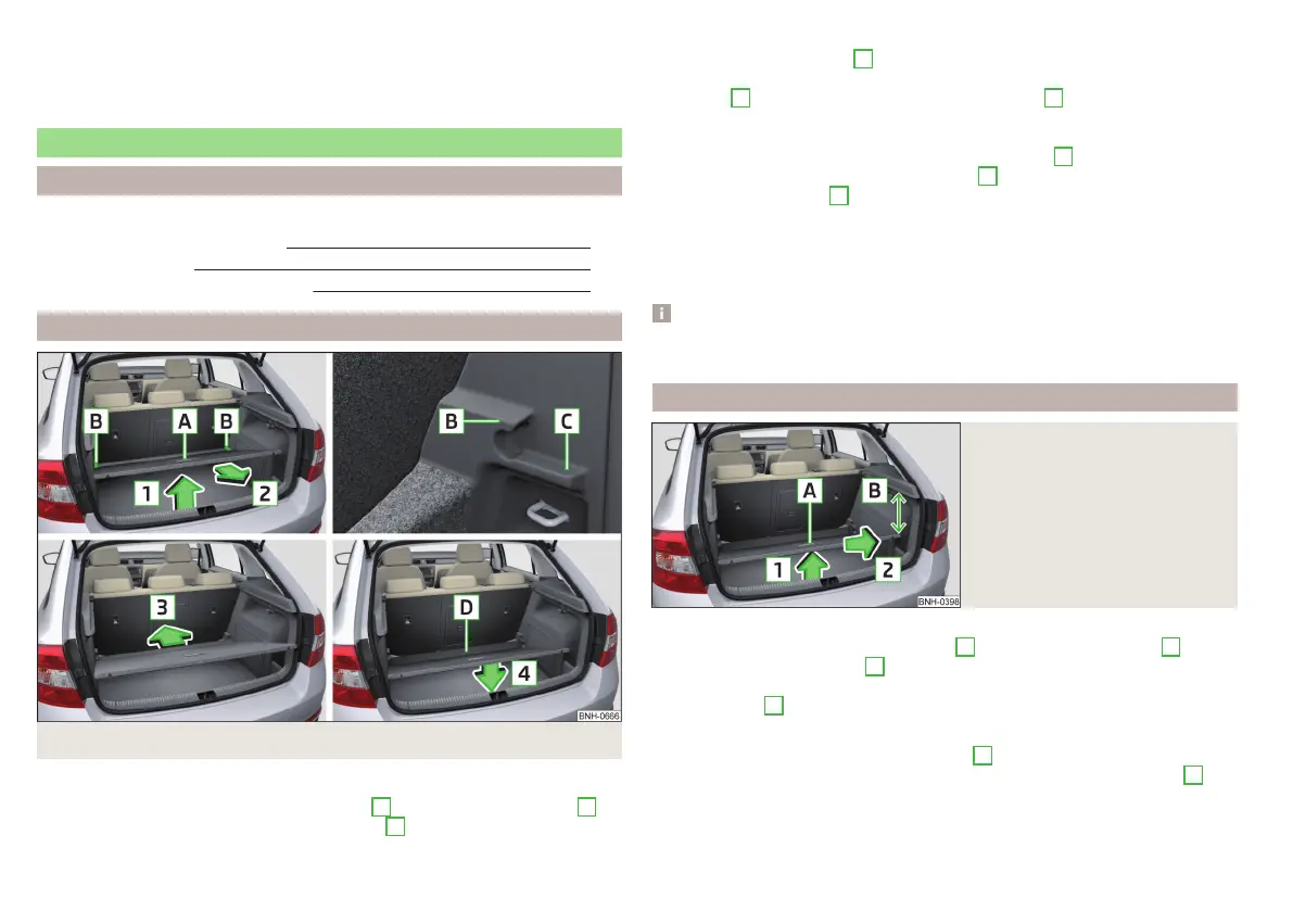
Set in the upper / lower position
Fig. 97 Set the variable loading floor to the upper/lower position
The variable loading floor can be set to the upper or lower position as follows.
›
Lift the variable loading floor by the handle
A
in the direction of arrow
1
and partially move it in the direction of arrow
2
» Fig. 97.
›
To set in the upper position, lift the variable loading floor in the front area
and position on the edge
C
.
›
To set in the lower position, move the variable loading floor in the direction
of arrow
2
until it removes itself from the mounts
B
, and position the front
of the variable loading floor on the floor covering of the luggage compart-
ment.
›
Insert the variable loading floor in direction of arrow
3
until it stops (when
set in the lower position, the front region
D
must be raised) and position in
the direction of arrow
4
.
The area under the variable loading floor can be used to stow small objects.
The maximum permissible load of the variable loading floor in the upper posi-
tion is 75 kg. For the transport of heavy loads, adjust the variable loading floor
in the lower position.
Note
The variable loading floor cannot be set in the upper/lower position when the
luggage compartment cover is in the “parking position” » page 78.
Removing/inserting
Fig. 98
Remove variable loading floor
Removing
›
Lift the variable loading floor at handle
A
in the direction of arrow
1
until
its rear area is about 15 cm
B
below the edge of the cover» Fig. 98.
›
Remove the variable loading floor from the vehicle by moving it in the direc-
tion of arrow
2
.
Inserting
›
Grasp the variable loading floor at handle
A
» Fig. 98.
›
Insert the variable loading floor, titled with the front area about 15 cm
B
be-
neath the edge of the cover, in the vehicle.
›
Then follow the same steps as when setting the upper position or the lower
position » page 80.
80
Using the system