Mid Size & Full Size RT’s
Engine Powered February 2008
SKYJACK, Page 15
Section 2 - Operation
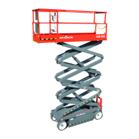
2.3 Major Assemblies
The aerial platform consists of three major assemblies:
base, lifting mechanism and platform.
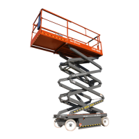
2.3-1 Base
The base is a rigid, one-piece weldment which supports
two side compartments.
Models 71xx & 88xx
One compartment contains the hydraulic and •
electrical components, and base control console.
The other compartment contains the fuel and
hydraulic tanks.
The propane cylinder is either located behind the •
access ladder or behind the fuel compartment.
The front axle is steered by a hydraulic cylinder •
and is either non-driven (2WD) or drive shaft/gear
box driven (4WD).
The rear axle is drive shaft/gear box driven and •
has a spring-applied hydraulically released disc
brake.
A roll-out tray at the front of the base supports an •
engine coupled with a two-section hydraulic pump
providing power to the hydraulic system.
An engine control console is also located at the •
front of the base.
The 12V starter battery is located in the hydraulic/•
electrical compartment or at the front of the engine
roll-out tray.
Model 9250
One compartment contains the hydraulic tank, •
hydraulic and electrical components, base control
console, emergency lowering battery and starter
battery.
The other compartment contains the fuel tank and •
Liquid Propane (LP) tank (if equipped).
The front axle is steered by a hydraulic cylinder •
and is either non-driven (2WD) or drive shaft/gear
box driven (4WD).
The rear axle is drive shaft/gear box driven and •
has two spring-applied hydraulically released
brakes.
A roll-out tray at the front of the base supports an •
engine coupled with a two-section hydraulic pump
providing power to the hydraulic system.
An engine control console is also located at the •
front of the base.
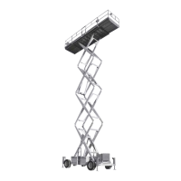
2.3-2 Lifting Mechanism
The lifting mechanism is constructed of formed steel or
tube sections making up a scissor-type assembly. The
scissor assembly is raised and lowered by single-acting
hydraulic lift cylinders with holding valves. A two-section
pump, driven by an engine, provides hydraulic power
to the lift cylinders.
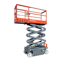
2.3-3 Platform
The platform is constructed of a tubular support frame,
a skid-resistant “diamond plate” platform surface and
39” hinged guardrails with 6” toe boards and mid-rails.
The platform can be entered from either side through
a spring-returned gate for full size RT’s and from the
rear through a spring-returned gate for mid Size RT’s.
The full size RT’s can be equipped with a front or rear
(or both) extension platform(s). The mid size RT’s are
equipped with a front extension platform. A 110V outlet
is also located on the platform.
2.4 Serial Number Nameplate
The serial number nameplate, located at the rear of the
aerial platform, lists the following:
Model number•
Serial number•
Aerial platform weight•
Maximum drivable height•
Maximum capacities•
Maximum number of persons permissible on •
the platform
Voltage•
System pressure•
Lift pressure•
Maximum platform height•
Maximum wheel load•
Maximum wind speed•
Maximum manual force•
Maximum incline •