14
5693
21 2023
-
SE60/185 s2
MC_0258
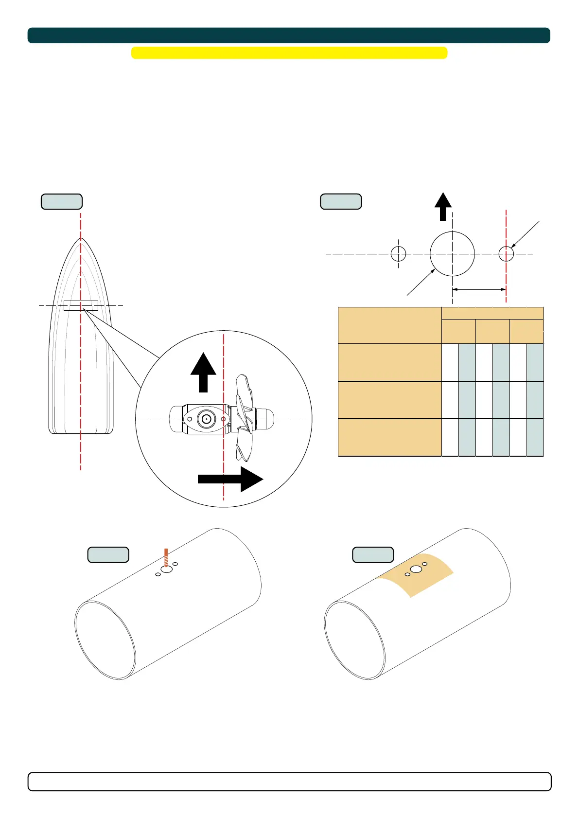
Gear Leg & Motor Bracket Installation
! Please refer to the graphic for special considerations relating to your model !
1. Mark the tunnel centreline and the boat’s centreline. (NB: Install the gear leg and propeller as shown for the thrust direction to correspond with
the control panel.)
2. Use the gasket or template (recommended) to mark the hole centres and double-check the measurements. One hole MUST be placed using
the boat centreline as shown above. (NB: All holes must be in-line with the tunnels’ centreline for correct installation, clearance between the
propeller and the tunnel is minimal.)
3. Drill the main centre hole followed by the two screw-holes.
4. Smooth the surface of the tunnel. A rough surface will cause possible failure/ movement of the gear leg. The motor bracket must rest steadily on
the tunnel.
MG_0616
Gasket
Gear leg
Test the propeller turns without
obstruction with tunnel wall
Motor
bracket
Bolt plate
7
Gasket
Bolt plate
Bracket
BOW
5
6
BOW
Bolt plate
MIN
MAX
Measure the drive shaft has come through the motor
bracket at the correct height with the template supplied.
The template must sit on the
bracket surface with the bolt
plate within the measurement
cutout
MIN
MAX
MG_0612
Tunnel
centre line
Tunnel
centre line
Drill centre hole first
Smooth surface area
Boats
centre line
Boats
centre line
Bow
Stern
B
ØC
ØA
BOW
1
2
STARBOARD
BOW
3 4
mm inch mm inch mm inch
SE20/110S
SE25/110S
28 1,1 20 0,8 7 0,3
SE/SEP/SE IP/SEP IP 30/125S2
SE/SEP/SE IP/SEP IP 40/125S2
28 1,1 21 0,8 8,5 0,3
SE/SEP/SE IP/SEP IP 30/140S
SE/SEP/SE IP/SEP IP 40/140S
SE/SEP/SE IP/SEP IP 50/140S
SE/SEP/SE IP/SEP IP 60/185S2
29 11 23 0,9 8,5 0,3
Models
Measurements