20
5693
21 2023
-
SE60/185 s2
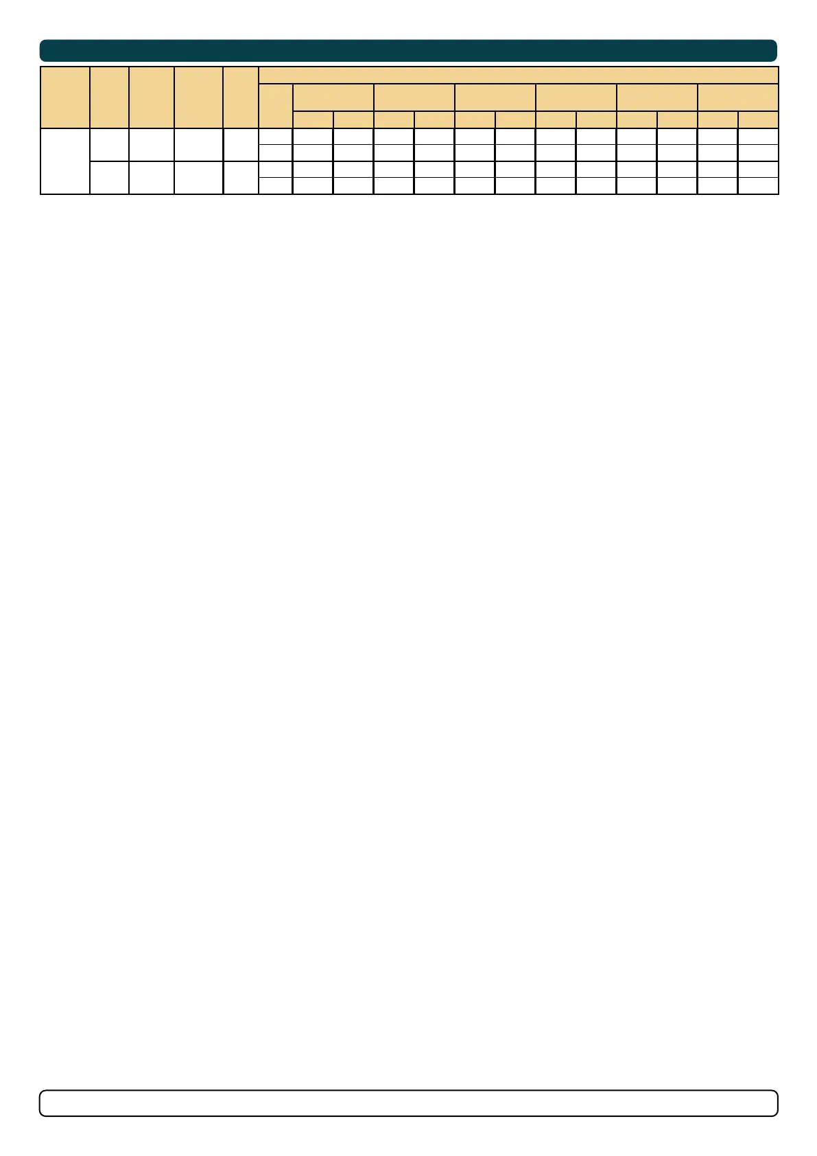
Electrical Reference Guide
MC_0617
Model Size
System
Voltage
Nominal
current
*Min.
battery
CCA
Rec.
fuse
Cross Section Guide for Power Cables
Unit
<7m
total + & -
7-14m
total + & -
15-21m
total + & -
22-28m
total + & -
28-35m
total + & -
36-45m
total + & -
Min. Rec. Min. Rec. Min. Rec. Min. Rec. Min. Rec. Min. Rec.
60/185S
60/140
12V 370 A
DIN: 350
SAE: 665
EN: 600
ANL 325
mm² 50 50 70 95 120 2 x 70 2 x 70 2 x 95 2 x 95 2 x 120 2 x 120 2 x 120
AWG 1/0 1/0 2/0 3/0 4/0 2 x 2/0 2 x 2/0 2 x 3/0 2 x 3/0 2 x 4/0 2 x 4/0 2 x 4/0
24V 170 A
DIN: 175
SAE: 332
EN: 280
ANL 150
mm² 25 25 25 35 35 50 35 50 50 70 70 70
AWG 3 3 3 2 2 1/0 2 1/0 1/0 2/0 2/0 2/0
MG_0590
++
12V
BATTERY
++
12V
BATTERY
Manual Main Switch Wiring Diagram 12V Thruster
ANL Fuse
ANL Fuse
Thruster
4-wire cable
4-wire cable
Thruster
Fuse 10A
Manual Main
Switch
Manual Main
Switch
The Top wiring diagram is for a single bow or stern thruster system
The top and bottom wiring diagram is for a dual thruster system, for example a bow and stern installation.
Refer to the User and Installation
Manual of the control panel for
detailed installation instructions.
Control
panel